Next: Initial Conditions
Up: Finite Difference Interpretation
Previous: MDWD Networks as Multi-step
Numerical Phase Velocity and Parasitic Modes
Because, in general, the image MDWDF of a given MDKC for a system of PDEs is a multi-step numerical integration scheme, it is reasonable to expect that parasitic modes [176] will be present in the solution. Energy in such modes often travels at speeds other than the desired wave speed in the medium, and may be highly oscillatory. If the scheme is consistent with the original system of PDEs, and stable, as is an MDWD network derived from the equivalent MDKC under the application of the trapezoid rule, then these parasitic modes must disappear in the limit as the time step is decreased (by the Lax-Richtmeyer Equivalence Theorem [176]). They have not as yet been addressed in the wave digital theory, and the subject is related to how initial conditions should be set in a MDWDF. The subject of initialization has been touched on only very briefly in [106].
Analysis of parasitic modes is easiest in the constant-coefficient case. We will examine the simplest possible non-trivial MDWDF, namely that of the constant-coefficient lossless source-free (1+1)D transmission line. Because at the stability limit, this scheme becomes equivalent to simple centered differences (see previous section), for which we do not have parasitic modes at all, we will look at the MDWDF of Figure 3.14(b) away from this limit . We have chosen
 . The MDWDF is redrawn in Figure 3.21, where we have
for some
 .
.
Figure 3.21:
Steady-state MDWD network for the lossless, source-free constant-coefficient (1+1)D transmission-line equations.
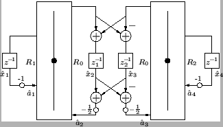 |
Note that because the system is now linear and shift-invariant, we have replaced the shifts
 and
and
 in the two directions
  and
and  by their frequency domain counterparts
 and
and
 . Recall also that we have, from (3.47) and (3.48), that
where  represents a unit delay in the time direction, and
  a unit shift in the
  direction. We have written the outputs of the delay registers, in an exponential state, as
where the
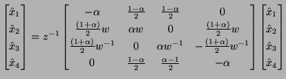
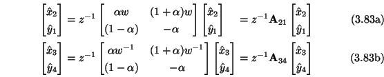
 are complex amplitudes. The updating of the values in the delay registers can be written, in terms of these amplitudes, as
which is parametrized by a reflectance
 |
(3.83) |
If we introduce the variables
the updating decouples into two subsystems, namely
 and
and
 are known as spectral amplification matrices (see Appendix A).
The symbols [176] of the two subsystems,
 and
and
 are defined by
where
 is the
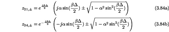
  identity matrix. Nontrivial solutions to the update equations (3.83) occur when the determinants of the symbols vanish. In the absence of boundary conditions, we may assume
 , where
  is a real wavenumber, in which case we have four solutions in terms of
  given by
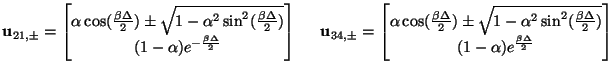
which are simply the eigenvalues of the spectral amplification matrices. The corresponding eigenvectors of these same matrices are
All four eigenvalues are of unit magnitude, and thus, using
 , we can rewrite solutions (3.84) as
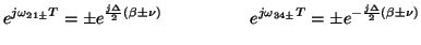 |
(3.86) |
for some real  defined by
 . ( always exists because we have
 , from (3.82).) For small wavenumbers, we have
and we thus have in this limit, for the roots subscripted with  in (3.85),
where we have used the fact that
 , which follows from (3.82) and the definitions of the port resistances in (3.64) as well as
 . The quantities
 and
and
 are called numerical phase velocities [176]; they approach the propagation speed in the medium, from (3.58), and these two solutions are to be interpreted as approximations to the traveling wave solution to the transmission line equations. The other modes, however, are parasitic, in that they do not propagate near the physical velocity. They are not problematic, provided initial conditions are set properly; indeed, in the limit as
  becomes small, any reasonable initial conditions tend to align the system with the dominant traveling modes of the system.
Clearly, if we are at the passivity limit, where
 , then
  , and thus
 , which implies, finally that
 , so that we have, from (3.85), that
 and
and
 ; wave propagation is thus dispersionless. As mentioned in the previous section, at this limit, the MDWD network reduces to an exact digital traveling wave solution (this was also noted in §3.7.5). It is also interesting to note that when
 , so that
  and are zero, then (3.85) implies that wave propagation is also dispersionless in this case as well. It is easy to see here, from Figure 3.21, that because
, there will be no scattering through the adaptors; the pure time delays may thus be shifted directly into the lattice two port, and we can perform a manipulation similar to that of §3.7.5 to give a simplified digital ``traveling wave'' network, with doubled time delays. Here, we are in effect implementing a traveling wave solution on a different grid, but the implication is that for the corresponding problem with material variation, the MDWD network gives a good approximation to the numerical phase velocity even for certain values of
and are zero, then (3.85) implies that wave propagation is also dispersionless in this case as well. It is easy to see here, from Figure 3.21, that because
, there will be no scattering through the adaptors; the pure time delays may thus be shifted directly into the lattice two port, and we can perform a manipulation similar to that of §3.7.5 to give a simplified digital ``traveling wave'' network, with doubled time delays. Here, we are in effect implementing a traveling wave solution on a different grid, but the implication is that for the corresponding problem with material variation, the MDWD network gives a good approximation to the numerical phase velocity even for certain values of  which are far from the local physical wave speed. This is not true for digital waveguide networks, where the numerical phase velocities degrade considerably away from the passivity limit. We will return to these expressions (which provide complete information regarding the numerical dispersion properties of the scheme) in §4.3.8 in a comparison with the digital waveguide network for the same system.
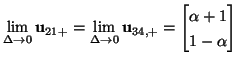
In anticipation of the discussion in §3.10, we mention that for constant , we have for the eigenvectors corresponding to the dominant modes, that
which are far from the local physical wave speed. This is not true for digital waveguide networks, where the numerical phase velocities degrade considerably away from the passivity limit. We will return to these expressions (which provide complete information regarding the numerical dispersion properties of the scheme) in §4.3.8 in a comparison with the digital waveguide network for the same system.
In anticipation of the discussion in §3.10, we mention that for constant , we have for the eigenvectors corresponding to the dominant modes, that
Because we also have, from Figure 3.21, that
 , and
, and
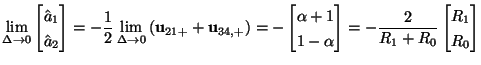
 , we can also write, for the dominant mode,
Thus in this limit, the wave variables incident on the left adaptor occur in the same ratio as the port resistances, and are in fact aligned with an eigenvector of the scattering matrix corresponding to the adaptor. A similar statement holds for the quantities incident on the right adaptor. We will return to this observation in the next section.
Next: Initial Conditions
Up: Finite Difference Interpretation
Previous: MDWD Networks as Multi-step
Stefan Bilbao
2002-01-22