

Next: Energetic Interpretation
Up: The (1+1)D Transmission Line
Previous: Digression: Derivation of an
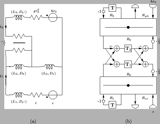
Returning to Figure 3.14(a), and making use of the discrete two-port derived in the last section, we can now write the complete wave digital network. It is shown in Figure 3.14(b).
Figure 3.14: (a) MD-passive network for the (1+1)D transmission line equations and (b) its associated MDWD network.
 |
The inductances in the MDKC of Figure 3.14(a) are
 |
(3.59) |
and the port resistances of the MDWD network of Figure 3.14(b) are
 |
(3.60) |
The MDWD network is MD-passive if all the port resistances are non-negative over the entire spatial domain; from (3.63) and (3.64), the only port resistances which are possibly negative are  and
and  . Requiring their positivity gives the constraints
where
 and
and
 .
A judicious choice of
 [131] allows the largest possible time step for a given grid spacing; the condition is then
 |
(3.61) |
where
 is defined by (3.59).
If  and
and  are constant, and (3.65) holds with equality, so that we have
 |
(3.62) |
then the MDWD numerical scheme is said to be operating at the Courant-Friedrichs-Lewy (CFL) bound [176]. For varying coefficients, however,  is bounded away from
 , so the time step will have to be chosen smaller than might be expected; we will look at how to improve upon this bound in §3.12.


Next: Energetic Interpretation
Up: The (1+1)D Transmission Line
Previous: Digression: Derivation of an
Stefan Bilbao
2002-01-22


![]() and
and ![]() . Requiring their positivity gives the constraints
. Requiring their positivity gives the constraints
![]() and
and ![]() are constant, and (3.65) holds with equality, so that we have
are constant, and (3.65) holds with equality, so that we have
