Next  |  Prev  |  Up  |  Top  |  Index  |  JOS Index  |  JOS Pubs  |  JOS Home  |  Search


The Clarinet Tonehole as a Two-Port Junction

Figure 9.43: Lumped-parameter description of the clarinet tonehole.
\includegraphics[scale=0.9]{eps/fFingerHoleKeefe}

The clarinet tonehole model developed by Keefe [242] is parametrized in terms of series and shunt resistance and reactance, as shown in Fig. 9.43. The transmission matrix description of this two-port is given by the product of the transmission matrices for the series impedance $ R_a/2$ , shunt impedance $ R_s$ , and series impedance $ R_a/2$ , respectively:

$\displaystyle \left[\begin{array}{c} P_1 \\ [2pt] U_1 \end{array}\right]$ $\displaystyle =$ $\displaystyle \left[\begin{array}{cc} 1 & R_a/2 \\ [2pt] 0 & 1 \end{array}\right]
\left[\begin{array}{cc} 1 & 0 \\ [2pt] R_s^{-1} & 1 \end{array}\right]
\left[\begin{array}{cc} 1 & R_a/2 \\ [2pt] 0 & 1 \end{array}\right]
\left[\begin{array}{c} P_2 \\ [2pt] U_2 \end{array}\right]$  
  $\displaystyle =$ $\displaystyle \left[\begin{array}{cc} 1+\frac{R_a}{2R_s} & R_a[1+\frac{R_a}{4R_s}]
\\ [2pt] \frac{1}{R_s} & 1+\frac{R_a}{2R_s} \end{array}\right]
\left[\begin{array}{c} P_2 \\ [2pt] U_2 \end{array}\right]$  

where all quantities are written in the frequency domain, and the impedance parameters are given by
(open-hole shunt impedance)$\displaystyle \quad R_s^o$ $\displaystyle =$ $\displaystyle R_b (j k t_e + \xi_e)$  
(closed-hole shunt impedance)$\displaystyle \quad R_s^c$ $\displaystyle =$ $\displaystyle -j R_b \cot(k t_h)$ (10.51)
(open-hole series impedance)$\displaystyle \quad R_a^o$ $\displaystyle =$ $\displaystyle -j R_b k t_a^o$  
(closed-hole series impedance)$\displaystyle \quad R_a^c$ $\displaystyle =$ $\displaystyle -j R_b k t_a^c$  

where $ R_b = \rho c / (\pi b^2)$ is the wave impedance of the tonehole entrance, i.e., that of an acoustic tube of cross-sectional area $ \pi b^2$ ($ \rho$ is air density and $ c$ is sound speed as usual), $ b$ is the tonehole radius, $ k = \omega/c = 2\pi/\lambda$ is the wavenumber (radian spatial frequency), $ t_e$ is the open-tonehole effective length (which is slightly greater than its physical length due to the formation of a small air-piston inside the open tonehole), $ \xi_e$ is the ``specific resistance'' of the open tonehole due to air viscosity in and radiation from the hole, $ t_h$ is the closed-tonehole height, defined such that its product times the cross-sectional area of the tonehole exactly equals the geometric volume $ V_h$ of the closed tonehole. Finally, $ t_a^o$ and $ t_a^c$ are the equivalent series lengths of the open and closed tonehole, respectively, and are given by
$\displaystyle t_a^o$ $\displaystyle =$ $\displaystyle \frac{0.47b (b/a)^4}{\tanh(1.84 t_h/b) + 0.62(b/a)^2 + 0.64 (b/a)}$  
$\displaystyle t_a^c$ $\displaystyle =$ $\displaystyle \frac{0.47b (b/a)^4}{\coth(1.84 t_h/b) + 0.62(b/a)^2 + 0.64 (b/a)}$  

where $ a$ is the radius of the main bore. The closed-tonehole height $ V_h/(\pi b^2)$ can be estimated as [242]

$\displaystyle t_h = t_w + \frac{1}{8}\frac{b^2}{a}\left[1+0.172\left(\frac{b}{a}\right)^2\right]
$

where $ t_w$ is the physical tonehole chimney height at its center.

Note that the specific resistance of the open tonehole, $ \xi_e$ , is the only real impedance and therefore the only source of wave energy loss at the tonehole. It is given by [242]

$\displaystyle \xi_e = 0.25 (kb)^2 + \alpha t_h + (1/4) k d_v\,$ln$\displaystyle (2b/r_c),
$

where $ r_c$ is the radius of curvature of the tonehole, $ d_v$ is the viscous-boundary-layer thickness which is expressible in terms of the shear viscosity $ \eta$ of air as

$\displaystyle d_v = \sqrt{\frac{2\eta}{\rho\omega}}
$

and $ \alpha$ is the real part of the propagation wavenumber (or minus the imaginary part of complex spatial frequency $ k$ ). In [241], for the large-tube limit (i.e., when the tube radius is large compared with the viscous boundary layer), $ \alpha$ is given by

$\displaystyle \alpha = \frac{1}{2bc}\left[\,\sqrt{\frac{2\eta\omega}{\rho}}
+ (\gamma-1)\sqrt{\frac{2\kappa\omega}{\rho C_p}}\,\right]
$

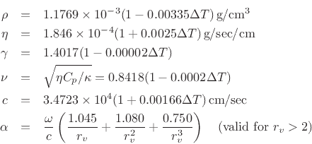
where $ \gamma=1.4$ is the adiabatic gas constant for air [321], $ \kappa$ is the thermal conductivity of air, and $ C_p$ is the specific heat of air at constant pressure. In [241], the following values are given for air at $ 300^\circ$ Kelvin ( $ 26.85^\circ$ C), and valid within $ \pm 10$ degrees of that temperature:

\begin{eqnarray*}
\rho &=& 1.1769 \times 10^{-3}(1-0.00335\Delta T)\,\mbox{g}/\mbox{cm}^3 \\
\eta &=& 1.846 \times 10^{-4}(1+0.0025\Delta T)\,\mbox{g}/\mbox{sec}/\mbox{cm} \\
\gamma &=& 1.4017 (1 - 0.00002\Delta T) \\
\nu &=& \sqrt{\eta C_p / \kappa} = 0.8418 (1 - 0.0002\Delta T) \\
c &=& 3.4723\times 10^4(1 + 0.00166\Delta T)\, \mbox{cm}/\mbox{sec} \\
\alpha &=& \frac{\omega}{c}
\left(\frac{1.045}{r_v} + \frac{1.080}{r_v^2} + \frac{0.750}{r_v^3} \right) \quad
\mbox{(valid for $r_v > 2$)}
\end{eqnarray*}

where

$\displaystyle r_v = b\sqrt{\frac{\rho\omega}{\eta}} = \sqrt{2}\frac{b}{d_v}
$

can be interpreted as $ \sqrt{2}$ times the ratio of the tonehole radius $ b$ to the viscous-boundary-layer thickness $ d_v$ [241]. The constant $ \nu^2$ is referred to as the Prandtl number, and $ \eta$ is the shear viscosity coefficient [241]. In [71], it is noted that $ r_v$ is greater than $ 8$ under practical conditions in musical acoustics, and so it is therefore sufficient to keep only the first and second-order terms in the expression above for $ \alpha$ .

The open-hole effective length $ t_e$ , assuming no pad above the hole, is given in [242] as

$\displaystyle t_e = \frac{(1/k)\tan(kt) + b [1.40 - 0.58(b/a)^2]}{1 - 0.61 kb \tan(kt)}
$

See [242] for the case in which a pad lies above the open hole. In [408], a unified tonehole model is given which supports continuous opening and closing of the tonehole.

For implementation in a digital waveguide model, the lumped parameters above must be converted to scattering parameters. Such formulations of toneholes have appeared in the literature: Vesa Välimäki [513,506] developed tonehole models based on a ``three-port'' digital waveguide junction loaded by an inertance, as described in Fletcher and Rossing [144], and also extended his results to the case of interpolated digital waveguides. It should be noted in this context, however, that in the terminology of Appendix C, Välimäki's tonehole representation is a loaded 2-port junction rather than a three-port junction. (A load can be considered formally equivalent to a ``waveguide'' having wave impedance given by the load impedance.) Scavone and Smith [405] developed digital waveguide tonehole models based on the more rigorous ``symmetric T'' acoustic model of Keefe [242], using general purpose digital filter design techniques to obtain rational approximations to the ideal tonehole frequency response. A detailed treatment appears in Scavone's CCRMA Ph.D. thesis [409]. This section, adapted from [467], considers an exact translation of the Keefe tonehole model, obtaining two one-filter implementations: the ``shared reflectance'' and ``shared transmittance'' forms. These forms are shown to be stable without introducing an approximation which neglects the series inertance terms in the tonehole model.

By substituting $ k=\omega/c$ in (9.53) to convert spatial frequency to temporal frequency, and by substituting

$\displaystyle P_i$ $\displaystyle =$ $\displaystyle P_i^{+}+ P_i^{-}$ (10.52)
$\displaystyle U_i$ $\displaystyle =$ $\displaystyle \frac{P_i^{+}- P_i^{-}}{R_0}$ (10.53)

for $ i=1,2$ , into (9.51) to convert physical variables to wave variables, ( $ R_0=\rho c /(\pi a^2)$ is the bore wave impedance), we may solve for the outgoing waves $ P_1^{-}, P_2^{-}$ in terms of the incoming waves $ P_1^{+}, P_2^{+}$ . Mathematica code for obtaining the general conversion formula from lumped parameters to scattering parameters is as follows:
 
        Clear["t*", "p*", "u*", "r*"]
        transmissionMatrix = {{t11, t12}, {t21, t22}};
        leftPort = {{p2p+p2m}, {(p2p-p2m)/r2}};
        rightPort = {{p1p+p1m}, {(p1p-p1m)/r1}};
        Format[t11, TeXForm] := "{T_{11}}"
        Format[p1p, TeXForm] := "{P_1^+}"
        ... (etc. for all variables) ...
        TeXForm[Simplify[Solve[leftPort == 
               transmissionMatrix . rightPort, {p1m, p2p}]]]
The above code produces the following formulas:
$\displaystyle P_1^-$ $\displaystyle =$ $\displaystyle \frac{2 {P_2^-} {R_1} - {P_1^+} {R_1} {T_{11}} -
{P_1^+} {T_{12}} +
{P_1^+} {R_1} {R_2} {T_{21}} +
{P_1^+} {R_2} {T_{22}}}{{R_1} {T_{11}} - {T_{12}} -
{R_1} {R_2} {T_{21}} + {R_2} {T_{22}}},$  
$\displaystyle P_2^+$ $\displaystyle =$ $\displaystyle \frac{{P_2^-} {R_1} {T_{11}} - {P_2^-} {T_{12}} +
{P_2^-} {R_1} {R_2} {T_{21}} -
2 {P_1^+} {R_2} {T_{12}} {T_{21}} -
{P_2^-} {R_2} {T_{22}} +
2 {P_1^+} {R_2} {T_{11}} {T_{22}}}{{R_1} {T_{11}} - {T_{12}} -
{R_1} {R_2} {T_{21}} + {R_2} {T_{22}}}$  
    $\displaystyle % Get eqn number on next line below
$ (10.54)

Substituting relevant values for Keefe's tonehole model, we obtain, in matrix notation,
$\displaystyle \left[\begin{array}{c} P_1^{-} \\ [2pt] P_2^{+} \end{array}\right]$ $\displaystyle =$ $\displaystyle \left[\begin{array}{cc} S & T \\ [2pt] T & S \end{array}\right]
\left[\begin{array}{c} P_1^{+} \\ [2pt] P_2^{-} \end{array}\right]$  
  $\displaystyle =$ $\displaystyle \frac{1}{(2R_0+R_a)(2R_0+R_a+4R_s)} \;\times$  
    $\displaystyle \quad
\left[\begin{array}{cc} 4R_aR_s + R_a^2 - 4R_0^2 & 8R_0R_s \\ [2pt] 8R_0R_s & 4R_aR_s + R_a^2 - 4R_0^2 \end{array}\right]
\left[\begin{array}{c} P_1^{+} \\ [2pt] P_2^{-} \end{array}\right]$ (10.55)

We thus obtain the scattering formulation depicted in Fig. 9.44, where

$\displaystyle S(\omega) = \frac{4R_aR_s + R_a^2 - 4R_0^2}{(2R_0+ R_a)(2R_0+ R_a + 4R_s)} \approx - \frac{R_0}{R_0+ 2R_s}$ (10.56)

is the reflectance of the tonehole (the same from either direction), and

$\displaystyle T(\omega) = \frac{8R_0R_s}{(2R_0+ R_a)(2R_0+ R_a + 4R_s)} \approx \frac{2R_s}{R_0+ 2R_s}$ (10.57)

is the transmittance of the tonehole (also the same from either direction). The notation ``$ S$ '' for reflectance is chosen because every reflectance is a Schur function (stable and not exceeding unit magnitude on the unit circle in the $ z$ plane) [432, p. 221].

Figure 9.44: Frequency-domain, traveling-wave description of the clarinet tonehole.
\includegraphics[scale=0.9]{eps/fFingerHoleScat}

The approximate forms in (9.57) and (9.58) are obtained by neglecting the negative series inertance $ R_a$ which serves to adjust the effective length of the bore, and which therefore can be implemented elsewhere in the interpolated delay-line calculation as discussed further below. The open and closed tonehole cases are obtained by substituting $ \{R_a = R_a^o,
R_s =
R_s^o\}$ and $ \{R_a = R_a^c, R_s =
R_s^c\}$ , respectively, from (9.53).

In a manner analogous to converting the four-multiply Kelly-Lochbaum (KL) scattering junction [247] into a one-multiply form (cf. (C.60) and (C.62) on page [*]), we may pursue a ``one-filter'' form of the waveguide tonehole model. However, the series inertance gives some initial trouble, since

$\displaystyle [1+S(\omega)] - T(\omega) = \frac{2R_a}{2R_0+ R_a} \isdef L(\omega)
$

instead of zero as in the KL junction. In the scattering formulas (C.100) and (C.101) on page [*] for the general loaded waveguide junction, the reflectance seen on any branch is always the transmittance from that branch to any other branch minus $ 1$ . I.e., if $ \alpha_i$ denotes the transmittance from branch $ i$ to all other branches meeting at the junction, then $ \alpha_i-1$ is the reflectance seen on branch $ i$ . Substituting

$\displaystyle T= 1 + S- L
$

into the basic scattering relations (9.56), and factoring out $ S$ , we obtain, in the frequency domain,
$\displaystyle P_1^{-}(\omega)$ $\displaystyle =$ $\displaystyle SP_1^{+}+ TP_2^{+}$  
  $\displaystyle =$ $\displaystyle SP_1^{+}+ [1 + S- L] P_2^{+}$  
  $\displaystyle =$ $\displaystyle S[P_1^{+}+ P_2^{+}] + [1 - L] P_2^{+}$  
  $\displaystyle \isdef$ $\displaystyle S[P_1^{+}+ P_2^{+}] + AP_2^{+}$ (10.58)

and, similarly,
$\displaystyle P_2^{-}(\omega)$ $\displaystyle =$ $\displaystyle S[P_1^{+}+ P_2^{+}] + AP_1^{+}$ (10.59)

The resulting tonehole implementation is shown in Fig. 9.45. We call this the ``shared reflectance'' form of the tonehole junction.

In the same way, an alternate form is obtained from the substitution

$\displaystyle S= T- 1 + L
$

which yields the ``shared transmittance'' form:
$\displaystyle P_1^{-}$ $\displaystyle =$ $\displaystyle T[P_1^{+}+ P_2^{+}] - AP_1^{+}$ (10.60)
$\displaystyle P_2^{-}$ $\displaystyle =$ $\displaystyle T[P_1^{+}+ P_2^{+}] - AP_2^{+}$ (10.61)

shown in Fig. 9.46.

Figure 9.45: ``Shared-reflectance'' implementation of the clarinet tonehole model.
\includegraphics[scale=0.9]{eps/fFingerHoleOneMul}

Figure 9.46: ``Shared-transmittance'' implementation of the clarinet tonehole model.
\includegraphics[scale=0.9]{eps/fFingerHoleOneMulAlt}

Figure 9.47: ``Shared-reflectance'' tonehole model with unstable allpasses pulled out to the inputs.
\includegraphics[scale=0.9]{eps/fFingerHoleOneMulCommuted}

Figure 9.48: ``Shared-transmittance'' tonehole model with unstable allpasses pulled out to inputs.
\includegraphics[width=\twidth]{eps/fFingerHoleOneMulAltCommuted}

Since $ L(\omega)\approx 0$ , it can be neglected to first order, and $ A(\omega)\approx 1$ , reducing both of the above forms to an approximate ``one-filter'' tonehole implementation.

Since $ R_a = -jR_b \omega t_a/c$ is a pure negative reactance, we have

$\displaystyle A(\omega) = 1 - L(\omega) = \frac{R_0- R_a/2}{R_0+ R_a/2} = \frac{p+j\omega}{p-j\omega}, \quad p=\frac{R_0c}{R_b t_a}$ (10.62)

In this form, it is clear that $ A(\omega)$ is a first-order allpass filter with a single pole-zero pair near infinity. Unfortunately, the pole is in the right-half-plane and hence unstable. We cannot therefore implement it as shown in Fig. 9.45 or Fig. 9.46. Using elementary manipulations, the unstable allpasses in Figs. 9.45 and Fig. 9.46 can be moved to the configuration shown in Figs. 9.47 and 9.48, respectively. Note that $ T(\omega)/A(\omega)$ is stable whenever $ T$ is stable. The unstable allpasses now operate only on the two incoming wave variables, and they can be implemented implicitly by slightly reducing the (interpolated) delay-lines leading to the junction from either side. The tonehole then requires only one filter $ S/A$ or $ T/A$ .

We now see precisely how the negative series inertance $ R_a$ provides a negative, frequency-dependent, length correction for the bore. From (9.63), the phase delay of $ A(\omega)$ can be computed as

$\displaystyle D_A(\omega) \isdef -\frac{\angle A(\omega)}{\omega}
= -2\tan^{-1}(\omega/p) = -2\tan^{-1}(k t_a R_b / R_0)
$

Thus, the negative delay correction goes to zero with frequency $ k=\omega/c$ , series tonehole length $ t_a$ , tonehole impedance $ R_b$ , or main bore admittance $ \Gamma _0= 1/R_0$ .

In practice, it is common to combine all delay corrections into a single ``tuning allpass filter'' for the whole bore [432,208]. Whenever the desired allpass delay goes negative, we simply add a sample of delay to the desired allpass phase-delay and subtract it from the nearest delay. In other words, negative delays have to be ``pulled out'' of the allpass and used to shorten an adjacent interpolated delay line. Such delay lines are normally available in practical modeling situations.


Next  |  Prev  |  Up  |  Top  |  Index  |  JOS Index  |  JOS Pubs  |  JOS Home  |  Search

[How to cite this work]  [Order a printed hardcopy]  [Comment on this page via email]

``Physical Audio Signal Processing'', by Julius O. Smith III, W3K Publishing, 2010, ISBN 978-0-9745607-2-4
Copyright © 2024-06-28 by Julius O. Smith III
Center for Computer Research in Music and Acoustics (CCRMA),   Stanford University
CCRMA