A (lossless) digital waveguide is defined as a
bidirectional delay line at some wave impedance ![]() [434,437].
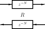
Figure 2.11 illustrates one digital waveguide.
[434,437].
Figure 2.11 illustrates one digital waveguide.
As before, each delay line contains a sampled acoustic traveling wave.
However, since we now have a bidirectional delay line, we have
two traveling waves, one to the ``left'' and one to the
``right'', say. It has been known since 1747 [100] that
the vibration of an ideal string
can be described as the sum of two traveling waves going in opposite
directions. (See Appendix C for a mathematical derivation of this
important fact.) Thus, while a single delay line can model an
acoustic plane wave, a bidirectional delay line (a digital
waveguide) can model any one-dimensional linear acoustic system such
as a violin string, clarinet bore, flute pipe, trumpet-valve pipe, or
the like. Of course, in real acoustic strings and bores, the 1D
waveguides exhibit some loss and
dispersion3.4 so that we will need some filtering in
the waveguide to obtain an accurate physical model of such systems.
The wave impedance ![]() (derived in Chapter 6) is
needed for connecting digital waveguides to other physical simulations
(such as another digital waveguide or finite-difference model).
(derived in Chapter 6) is
needed for connecting digital waveguides to other physical simulations
(such as another digital waveguide or finite-difference model).