| (10.18) |
To obtain a force-wave digital waveguide model of the string-mass assembly after the mass has struck the string, it only remains to digitize the model of Fig.9.20. The delays are obviously to be implemented using digital delay lines. For the mass, we must digitize the force reflectance appearing in the one-filter model of Fig.9.20:
The bilinear transform is typically scaled as
where
the bilinear transform gives
![\begin{eqnarray*}
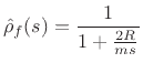
\hat{\rho}_d(z)
&=& \frac{1}{1+\frac{2R}{m}\frac{T}{2}\frac{1+z^{-1}}{1-z^{-1}}}\\ [5pt]
&=& g\frac{1-z^{-1}}{1-pz^{-1}}
\end{eqnarray*}](img2170.png)
where the gain coefficient ![]() and pole
and pole ![]() are given by
are given by
![\begin{eqnarray*}
g&\isdef &\frac{1}{1+\frac{RT}{m}}\;<\;1\\ [5pt]
p&\isdef &\frac{1-\frac{RT}{m}}{1+\frac{RT}{m}}\;<\;1.
\end{eqnarray*}](img2171.png)
Thus, the reflectance of the mass is a one-pole, one-zero filter. The
zero is exactly at dc, the real pole is close to dc, and the gain at
half the sampling rate is ![]() . We may recognize this as the classic
dc-blocking filter
[452]. Comparing with Eq.(9.18), we see that the behavior
at dc is correct, and that the behavior at infinite frequency
(
. We may recognize this as the classic
dc-blocking filter
[452]. Comparing with Eq.(9.18), we see that the behavior
at dc is correct, and that the behavior at infinite frequency
(
![]() ) is now the behavior at half the sampling rate
(
) is now the behavior at half the sampling rate
(
![]() ).
).
Physically, the mass reflectance is zero at dc because sufficiently slow waves can freely move a mass of any finite size. The reflectance is 1 at infinite frequency because there is no time for the mass to start moving before it is pushed in the opposite direction. In short, a mass behaves like a rigid termination at infinite frequency, and a free end (no termination) at zero frequency. The reflectance of a mass is therefore a ``dc blocker''.
The final digital waveguide model of the mass-string combination is shown in Fig.9.21.
Additional examples of lumped-element modeling, including masses, springs, dashpots, and their various interconnections, are discussed in the Wave Digital Filters (WDF) appendix (Appendix F). A nice feature of WDFs is that they employ traveling-wave input/output signals which are ideal for interfacing to digital waveguides. The main drawback is that the WDFs operate over a warped frequency axis (due to the bilinear transform), while digital delay lines have a normal (unwarped) frequency axis. On the plus side, WDFs cannot alias, while digital waveguides do alias in the frequency domain for signals that are not bandlimited to less than half the sampling rate. At low frequencies (or given sufficient oversampling), the WDF frequency warping is minimal, and in such cases, WDF ``lumped element models'' may be connected directly to digital waveguides, which are ``sampled-wave distributed parameter'' models.
Even when the bilinear-transform frequency-warping is severe, it is often well tolerated when the frequency response has only one ``important frequency'', such as a second-order resonator, lowpass, or highpass response. In other words, the bilinear transform can be scaled to map any single analog frequency to any desired corresponding digital frequency (see §7.3.2 for details), and the frequency-warped responses above and below the exactly mapped frequency may ``sound as good as'' the unwarped responses for musical purposes. If not, higher order filters can be used to model lumped elements (Chapter 7).
![\includegraphics[width=\twidth]{eps/massstringdwmz}](img2174.png)