Next: Scattering Junctions
Up: Digital Waveguides
Previous: Wave Equation Interpretation
Note on the Different Definitions of Wave Quantities
Waveguides are sometimes defined in a slightly different way [165], as pictured in Figure 4.2.
Figure 4.2:
Oriented bidirectional delay line.
 |
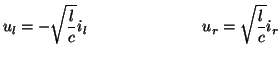
Now the superscripted + and  refer to a direction of propagation (to the right or left, respectively) rather than to outputs and inputs to the delay line pair. If we still assume (4.4a) and (4.4b) to hold for some positive impedance
  , then this definition of wave quantities implies that there is a direction associated with a particular waveguide--that is, a leftward () traveling current wave is sign-inverted with respect to the leftward traveling voltage wave, but the same is not true for the rightward traveling waves. It should be obvious that this definition of wave quantities also leads to a traveling wave solution of the wave equation (indeed, the bidirectional delay line of Figure 4.1 is identical to that of Figure 4.2 if we are using only voltage waves). The difference here is that we can now interpret the traveling wave pair
  to be a solution to the transmission line or telegrapher's equations [28], a set of two first order PDEs (from which the wave equation is often derived):
 |
(4.11a) |
which, for constant  and
and  has a solution
where
and  is again given by
 .
It should be remarked that if we had chosen the relationship between the wave variables to be such that (+) superscripted current wave were to be sign-inverted with respect to the (+) voltage wave, then we would be solving the ``mirror-image'' PDEs that one would get if one replaced
.
It should be remarked that if we had chosen the relationship between the wave variables to be such that (+) superscripted current wave were to be sign-inverted with respect to the (+) voltage wave, then we would be solving the ``mirror-image'' PDEs that one would get if one replaced  by
by  in system (4.11). The definition of wave variables (which we might call the ``input-output'' definition) given in §4.2.1 solves the wave equation which results from eliminating variables in system (4.11), or its mirror image, and hence does not have an orientation.
In practice, in order to proceed with numerical methods in systems of PDEs for which direction is important, we can either use the oriented wave variable definition given in this section, or we can use the input-output formulation, and reintroduce directionality into the network where appropriate. We have chosen the latter course, and we will indicate which changes must be made (usually through the use of transformers) explicitly on the signal flow graph. From a programmer's point of view, there is no substantial difference between the algorithms which develop using the different definitions. Both definitions lead to the same scattering equations (to be discussed in the next section) and are identical from a power conservation point of view (that is to say, sign-inversions of wave quantities do not affect the energy measure of the network).
An additional reason for choosing the input-output definition of wave variables is that it will require less notational juggling when we eventually link DWNs to MDWD networks in §4.10.
Next: Scattering Junctions
Up: Digital Waveguides
Previous: Wave Equation Interpretation
Stefan Bilbao
2002-01-22