


Next: Note on the Different
Up: Digital Waveguides
Previous: Impedance
Wave Equation Interpretation
The second-order PDE describing the voltage distribution  along an electrical transmission line with constant inductance and capacitance
  and
and  per unit length and which runs parallel to the
  -axis is
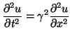 |
(4.7) |
where the wave speed  is
is
 . As we saw in §1.1.1, the solution to this equation, if we set aside boundary conditions for the moment, can be written in terms of traveling waves:
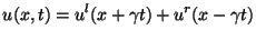 |
(4.8) |
That is, the solution at any time  is made up of a sum of two shifted copies of the initializing functions
  and
and  , which have traveled to the left and right respectively with velocity over a distance
  . For any
  we have, for the leftward-traveling wave, the identity
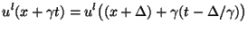 |
(4.9) |
If we set
 , then at time
  ,
,
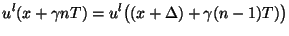 |
(4.10) |
Associate now with a particular waveguide a delay  and a physical length , so that in Figure 4.1
  represents an outgoing voltage wave quantity at position , and
  an incoming wave at position
  . It is then clear that if we have
 , then (4.10) is equivalent to the second equation of (4.1), with
  , and with
 and
and
 . A similar correspondence holds for the right-going traveling wave component
  and the wave variables at either end of the rightward waveguide,
  and
and  . A chain of bidirectional delay lines, connected in cascade will then implement an exact traveling wave solution to the wave equation. The physical voltage
  may be obtained (as should be clear from (4.8)) by summing the leftward and rightward traveling components at any particular location in the cascade, as per equation (4.3). Note that because
, the delay period and the waveguide length cannot be chosen independently, if the discrete wave quantities are to behave as traveling wave solutions to (4.7).
may be obtained (as should be clear from (4.8)) by summing the leftward and rightward traveling components at any particular location in the cascade, as per equation (4.3). Note that because
, the delay period and the waveguide length cannot be chosen independently, if the discrete wave quantities are to behave as traveling wave solutions to (4.7).
Next: Note on the Different
Up: Digital Waveguides
Previous: Impedance
Stefan Bilbao
2002-01-22