Next: Discretization in the Spectral
Up: MD Circuit Elements
Previous: The MD Inductor
The inductor and capacitor are the only circuit elements which need a more involved treatment in the MD case . The capacitor is treated as the dual to the inductor, replacing
  by
by  and
and  by
by  , and needs no further comment, other than that, as with the lumped capacitor, there is no sign inversion in the resulting MD wave one-port. The graphical representations of these MD one-ports and their MDWD equivalents are shown in Figure 3.5. Note that for the sake of compactness, in the circuit diagrams that will follow, we will use the derivative notation of the MDWDF literature [131] where we have
for some transformed coordinate  . In some instances, derivatives with respect to the original untransformed variables appear, and we will write
We will also use the notation
to refer to the dimensionless time derivative, which appears frequently. Also, in a signal flow graph, we represent the operation of shifting by  in direction by the symbol
 . In cases where the system or
  -port is linear and shift-invariant, we will be able to replace
by
-port is linear and shift-invariant, we will be able to replace
by
 , the transmittance of a shift in direction (see the next section).
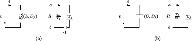
Figure 3.5:
MDWD one-ports-- (a) an MD inductor, with inductance , direction and its MDWD counterpart, for step-size and
 and (b) an MD capacitor, of capacitance , direction and its MDWD one-port, with step-size and port resistance
 .
.
 |
All the other elements for which we will have a use, namely the resistor, transformer and gyrator, as well as scattering junctions are memoryless and hence their pointwise behavior in MD is identical to that of their lumped counterparts. Their graphical representations are also identical (see §2.2.4). We must keep in mind however, that these are still distributed elements. For example, a resistor of resistance
 in an MDKC represents some resistivity at every point in the domain of the problem.
A network made up of Kirchoff connections of -ports which are individually MD-passive can be shown (through the use of Tellegen's Theorem [136], which is unchanged in multiple dimensions) to be be MD-passive as a whole [44].
Next: Discretization in the Spectral
Up: MD Circuit Elements
Previous: The MD Inductor
Stefan Bilbao
2002-01-22