


Next: Initial Conditions
Up: Boundary Conditions
Previous: Grid Arrangement Requiring Voltage
Termination of the other type of mesh, as shown in Figure 4.23(b) is comparatively simple, because the series junctions are isolated from one another along the boundary itself. Terminations for both types of boundary conditions are shown in Figure 4.25.
Figure 4.25:
(2+1)D waveguide mesh terminations at a southern boundary, for the grid of Figure 4.23(b)-- for (a)
 and (b)
 .
.
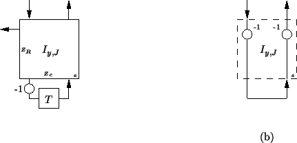 |
The boundary condition  can be simply implemented by terminating the series boundary junctions in open circuits. The condition
  can be ensured by through proper adjustment of the self-loop impedance, depending on the type of waveguide mesh. The settings will be
The positivity condition on the boundary self-loop impedances for the type I mesh again does not degrade the stability bound over the mesh interior. As for interior series junctions, we will have
 at the boundary junctions.
This type of mesh possesses an additional advantage--if we are working on a rectangular domain, then the ``holes'' in the staggered grid (that is, those points at which neither  nor
nor  is calculated, as per Figure 4.18) may be placed at the corners of the domain. The extra programming task of specializing the waveguide mesh at the corners can then be safely ignored.
All results can of course be extended, by symmetry, to any edge of a rectangular domain.
Next: Initial Conditions
Up: Boundary Conditions
Previous: Grid Arrangement Requiring Voltage
Stefan Bilbao
2002-01-22