Next  |  Prev  |  Up  |  Top  |  Index  |  JOS Index  |  JOS Pubs  |  JOS Home  |  Search


Phasing with First-Order Allpass Filters

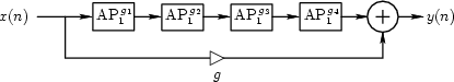
The block diagram of a typical inexpensive phase shifter for guitar players is shown in Fig. 3.10. It consists of a series chain of first-order allpass filters,4.4 each having a single time-varying parameter $ g_i(n)$ controlling the pole and zero location over time, plus a feedforward path through gain $ g$ which is a fixed depth control.

Figure 3.10: Structure of a phaser based on four first-order allpass filters.
\begin{figure}\input fig/allpass1phaser.pstex_t
\end{figure}

In analog hardware, the first-order allpass transfer function [426, Appendix C, Section 8]4.5is

$\displaystyle \hbox{AP}_{1}^{\,\omega_b} \isdef \frac{s-\omega_b}{s+\omega_b}. \protect$ (4.4)

In discrete time, the general first-order allpass has the transfer function

$\displaystyle \hbox{AP}_{1}^{\,g_i} \isdef \frac{g_i + z^{-1}}{1 + g_i z^{-1}}.
$

We now consider the analog and digital cases, respectively.


Subsections
Next  |  Prev  |  Up  |  Top  |  Index  |  JOS Index  |  JOS Pubs  |  JOS Home  |  Search

[How to cite and copy this work] 
``Physical Audio Signal Processing for Virtual Musical Instruments and Digital Audio Effects'', by Julius O. Smith III, (December 2005 Edition).
Copyright © 2006-07-01 by Julius O. Smith III
Center for Computer Research in Music and Acoustics (CCRMA),   Stanford University
CCRMA  [Automatic-links disclaimer]