To create a virtual analog phaser, following closely the design
of typical analog phasers, we must translate each first-order allpass
to the digital domain. Working with the transfer function, we must
map from ![]() plane to the
plane to the ![]() plane. There are several ways to
accomplish this goal [340]. However, in this case,
an excellent choice is the bilinear transform (see §J.4),
defined by
plane. There are several ways to
accomplish this goal [340]. However, in this case,
an excellent choice is the bilinear transform (see §J.4),
defined by
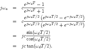
Thus, given a particular desired break frequency
![]() , we can set
, we can set
Recall from Eq. (3.4) that the transfer function of the first-order analog allpass filter is given by
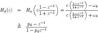
where we have denoted the pole of the digital allpass by
Figure 3.12 shows the digital phaser response curves corresponding to the analog
response curves in Fig. 3.11. While the break frequencies are
preserved by construction, the notches have moved slightly, although
this is not visible from the plots. An overlay of the total phase of
the analog and digital allpass chains is shown in Fig. 3.13.
We see that the phase responses of the analog and digital alpass
chains diverge visibly only above 9 kHz. The analog phase response
approaches zero in the limit as
![]() , while the digital
phase response reaches zero at half the sampling rate,
, while the digital
phase response reaches zero at half the sampling rate, ![]() kHz in
this case. This is a good example of when the bilinear transform
performs very well.
kHz in
this case. This is a good example of when the bilinear transform
performs very well.
![\includegraphics[width=\twidth]{eps/phaser1d}](img605.png) |
![\includegraphics[width=\twidth]{eps/phaser1ad}](img606.png) |