Next |
Prev |
Up |
Top
|
Index |
JOS Index |
JOS Pubs |
JOS Home |
Search
It seems reasonable to expect that the tonehole should be
representable as a load along a waveguide bore model, thus
creating a loaded two-port junction with two identical bore ports on
either side of the tonehole. From the relations for the loaded
parallel junction (C.101), in the two-port case
with
 , and considering pressure waves rather than force
waves, we have
, and considering pressure waves rather than force
waves, we have
Thus, the loaded two-port junction can be implemented in ``one-filter
form'' as shown in Fig. 9.48 with
 (
(
 ) and
) and
Comparing with (9.58), we see that the simplified Keefe tonehole
model with the negative series inertance removed ( ), is
equivalent to a loaded two-port waveguide junction with
), is
equivalent to a loaded two-port waveguide junction with  ,
i.e., the parallel load impedance is simply the shunt impedance in the
tonehole model.
,
i.e., the parallel load impedance is simply the shunt impedance in the
tonehole model.
Each series impedance  in the split-T model of
Fig. 9.43 can be modeled as a series waveguide
junction with a load of
. To see this, set the transmission
matrix parameters in (9.55) to the values
in the split-T model of
Fig. 9.43 can be modeled as a series waveguide
junction with a load of
. To see this, set the transmission
matrix parameters in (9.55) to the values
 ,
,
 , and
, and  from (9.51) to get
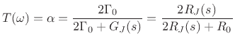
where
 is the alpha parameter for a series
loaded waveguide junction involving two impedance
is the alpha parameter for a series
loaded waveguide junction involving two impedance  waveguides joined
in series with each other and with a load impedance of
, as
can be seen from (C.99). To obtain exactly the loaded series
scattering relations (C.100), we first switch to the more general
convention in which the ``
waveguides joined
in series with each other and with a load impedance of
, as
can be seen from (C.99). To obtain exactly the loaded series
scattering relations (C.100), we first switch to the more general
convention in which the `` '' superscript denotes waves traveling into a junction of any number of waveguides. This exchanges ``
'' with ``
'' superscript denotes waves traveling into a junction of any number of waveguides. This exchanges ``
'' with ``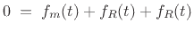 ''
at port 2 to yield
''
at port 2 to yield
Next we convert pressure to velocity using
 and
and
 to obtain
Finally, we toggle the reference direction of port 2 (the ``current'' arrow
for  on port 2 in Fig. 9.43) so that velocity is
positive flowing into the junction on both ports (which is the
convention used to derive (C.100) and which is typically followed
in circuit theory). This amounts to negating
on port 2 in Fig. 9.43) so that velocity is
positive flowing into the junction on both ports (which is the
convention used to derive (C.100) and which is typically followed
in circuit theory). This amounts to negating  , giving
where
 .
This is then the canonical form (C.100).
.
This is then the canonical form (C.100).
Next |
Prev |
Up |
Top
|
Index |
JOS Index |
JOS Pubs |
JOS Home |
Search
[How to cite this work] [Order a printed hardcopy] [Comment on this page via email]