In this section, scattering relations will be derived for the general
case of N waveguides meeting at a load. When a load is
present, the scattering is no longer lossless, unless the load itself
is lossless. (i.e., its impedance has a zero real part). For ![]() ,
,
![]() will denote a velocity wave traveling into the junction,
and will be called an ``incoming'' velocity wave as opposed to
``right-going.''C.9
will denote a velocity wave traveling into the junction,
and will be called an ``incoming'' velocity wave as opposed to
``right-going.''C.9
![\includegraphics[width=\twidth]{eps/fNstrings}](img3936.png) |
Consider first the series junction of ![]() waveguides
containing transverse force and velocity waves. At a series junction,
there is a common velocity while the forces sum. For definiteness, we
may think of
waveguides
containing transverse force and velocity waves. At a series junction,
there is a common velocity while the forces sum. For definiteness, we
may think of ![]() ideal strings intersecting at a single point, and the
intersection point can be attached to a lumped load impedance
ideal strings intersecting at a single point, and the
intersection point can be attached to a lumped load impedance
![]() , as depicted in Fig.C.29 for
, as depicted in Fig.C.29 for ![]() . The presence of
the lumped load means we need to look at the wave variables in the
frequency domain, i.e.,
. The presence of
the lumped load means we need to look at the wave variables in the
frequency domain, i.e.,
![]() for velocity waves and
for velocity waves and
![]() for force waves, where
for force waves, where
![]() denotes
the Laplace transform. In the discrete-time case, we use the
denotes
the Laplace transform. In the discrete-time case, we use the ![]() transform instead, but otherwise the story is identical. The physical
constraints at the junction are
transform instead, but otherwise the story is identical. The physical
constraints at the junction are
| (C.90) | |||
 |
(C.91) |
The parallel junction is characterized by
| (C.92) | |||
 |
(C.93) |
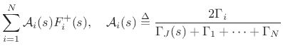
The scattering relations for the series junction are derived as
follows, dropping the common argument `![]() ' for simplicity:
' for simplicity:
 |
(C.94) | ||
 |
(C.95) | ||
 |
(C.96) |
Similarly, the scattering relations for the loaded parallel junction
are given by
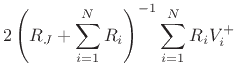
It is interesting to note that the junction load is equivalent to an
![]() st waveguide having a (generalized) wave impedance given by the
load impedance. This makes sense when one recalls that a transmission
line can be ``perfectly terminated'' (i.e., suppressing all
reflections from the termination) using a lumped resistor equal in
value to the wave impedance of the transmission line. Thus, as far as
a traveling wave is concerned, there is no difference between a wave
impedance and a lumped impedance of the same value.
st waveguide having a (generalized) wave impedance given by the
load impedance. This makes sense when one recalls that a transmission
line can be ``perfectly terminated'' (i.e., suppressing all
reflections from the termination) using a lumped resistor equal in
value to the wave impedance of the transmission line. Thus, as far as
a traveling wave is concerned, there is no difference between a wave
impedance and a lumped impedance of the same value.