The summation in Eq.(4.13) cannot be implemented in practice because
the ``ideal lowpass filter'' impulse response ![]() actually extends
from minus infinity to infinity. It is necessary in practice to window the ideal impulse response so as to make it finite. This is the basis
of the window method for digital filter design
[115,365]. While many other filter design techniques
exist, the window method is simple and robust, especially for very
long impulse responses. In the case of the algorithm presented below,
the filter impulse response is very long because it is heavily
oversampled. Another approach is to design optimal decimated
``sub-phases'' of the filter impulse response, which are then
interpolated to provide the ``continuous'' impulse response needed for
the algorithm [361].
actually extends
from minus infinity to infinity. It is necessary in practice to window the ideal impulse response so as to make it finite. This is the basis
of the window method for digital filter design
[115,365]. While many other filter design techniques
exist, the window method is simple and robust, especially for very
long impulse responses. In the case of the algorithm presented below,
the filter impulse response is very long because it is heavily
oversampled. Another approach is to design optimal decimated
``sub-phases'' of the filter impulse response, which are then
interpolated to provide the ``continuous'' impulse response needed for
the algorithm [361].
Figure 4.23 shows the frequency response of the ideal
lowpass filter. This is just the Fourier transform of ![]() .
.
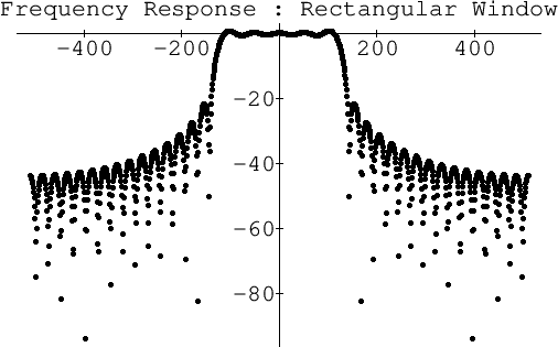
If we truncate ![]() at the fifth zero-crossing to the left and the
right of the origin, we obtain the frequency response shown in
Fig.4.24. Note that the stopband exhibits only slightly
more than 20 dB rejection.
at the fifth zero-crossing to the left and the
right of the origin, we obtain the frequency response shown in
Fig.4.24. Note that the stopband exhibits only slightly
more than 20 dB rejection.
 |
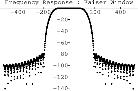
If we instead use the Kaiser window [222,442] to
taper ![]() to zero by the fifth zero-crossing to the left and the
right of the origin, we obtain the frequency response shown in
Fig.4.25. Note that now the stopband starts out close to
to zero by the fifth zero-crossing to the left and the
right of the origin, we obtain the frequency response shown in
Fig.4.25. Note that now the stopband starts out close to
![]() dB. The Kaiser window has a single parameter which can be used
to modify the stop-band attenuation, trading it against the transition
width from pass-band to stop-band.
dB. The Kaiser window has a single parameter which can be used
to modify the stop-band attenuation, trading it against the transition
width from pass-band to stop-band.
 |
