Next  |  Prev  |  Up  |  Top  |  Index  |  JOS Index  |  JOS Pubs  |  JOS Home  |  Search


Finite Impulse Response Digital Filters

In §5.1 we defined the general difference equation for IIR filters, and a couple of second-order examples were diagrammed in Fig.5.1. In this section, we take a more detailed look at the special case of Finite Impulse Response (FIR) digital filters. In addition to introducing various terminology and practical considerations associated with FIR filters, we'll look at a preview of transfer-function analysis (Chapter 6) for this simple special case.

Figure: The general, causal, length $ N=M+1$ , finite-impulse-response (FIR) digital filter. For FIR filters, direct-form I and direct-form II are the same (see Chapter 9).
\includegraphics{eps/fir}

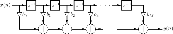
Figure 5.5 gives the signal flow graph for a general causal FIR filter Such a filter is also called a transversal filter, or a tapped delay line. The implementation shown is classified as a direct-form implementation.


Subsections
Next  |  Prev  |  Up  |  Top  |  Index  |  JOS Index  |  JOS Pubs  |  JOS Home  |  Search

[How to cite this work]  [Order a printed hardcopy]  [Comment on this page via email]

``Introduction to Digital Filters with Audio Applications'', by Julius O. Smith III, (September 2007 Edition)
Copyright © 2023-09-17 by Julius O. Smith III
Center for Computer Research in Music and Acoustics (CCRMA),   Stanford University
CCRMA