Next: Music and Audio Applications
Up: Vector Waveguides and Scattering
Previous: Vector Waveguides and Scattering
Vector/Scalar Waveguide Coupling
In a few cases, it is useful to have a means of connecting vector and scalar network elements. This comes up when designing networks to simulate mixed vector/scalar systems of PDEs; in particular, it will be necessary to use vector methods when working in non-orthogonal coordinate systems (see §4.8) and in the WDF context for some of the mechanical systems of Chapter 5.
We will always assume that for any given scattering junction, the number of components of any approaching wave is the same at every port; it may not be, however, that every junction in the network accepts waves with some universal number of components. In particular, a vector waveguide, one of whose ends is connected to a vector junction may be split into several scalar waveguides, or more generally into a number of vector waveguides each with a smaller number of components. Similarly, it is possible to ``bundle'' several waveguides into a single larger waveguide.
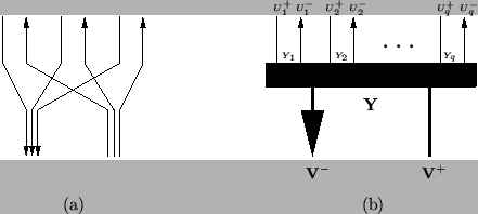
Let us assume that all splittings and bundlings are from vector to strictly scalar and scalar to vector respectively. An element which splits a single three-component waveguide into three scalar waveguides is shown in Figure 4.4(a), and its simplified graphical representation for arbitrary  in (b).
Figure 4.4: (a) Element for splitting of a vector waveguide into three scalar waveguides and (b) a simplified graphical representation in the general case of scalar waveguides.
 |
In (b) the admittance of the  th scalar waveguide,
 is
is  , and the voltage waves entering and leaving the splitter at the connection with this waveguide are
  and
and  . On the other side of the connection, we have a single -vector waveguide, of matrix admittance
  . The column vector voltage waves entering and leaving the connection are
 and
and
 . In order for this connection to make sense, we must choose
 , and order the splitting such that the th components of
 and
and
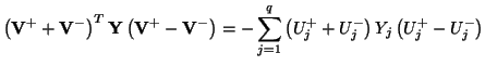
 are equal to and respectively; such an ordering for a 1:3 splitting is shown in (a). In this case, it is easy to see that energy is conserved across such a connection (indeed, if the scalar waveguides are thought of as acoustic tubes, then the black bar in (b) is merely equivalent to a ``rubber band'' joining them). The power entering the connection from the vector side can be written as
which is the total power leaving the connection through the scalar waveguides. It is important to note that such a connection can not be viewed as a multi-port element. In addition, passivity is contingent upon this choice of . It is easy to generalize this picture to a connection which splits a vector waveguide into various smaller vector waves (instead of scalars). In that case, should be chosen to be the block diagonal ``direct sum'' of the various matrix admittances on the other side of the connection.
Next: Music and Audio Applications
Up: Vector Waveguides and Scattering
Previous: Vector Waveguides and Scattering
Stefan Bilbao
2002-01-22