Next: Vector/Scalar Waveguide Coupling
Up: Digital Waveguides
Previous: Scattering Junctions
It is also possible to extend a DWN to the vector case [167,169]; this has also been done in the WDF framework in [46,131], as discussed in §2.3.7. We briefly introduce vector waveguides, because it will be necessary to apply them when simulating the behavior of stiff systems and elastic solids; we will examine this problem in depth in Chapter 5.
A vector waveguide accepts two incoming signals
 and
and
 and outputs
 and
and
 ; all are assumed to be
  vectors (note that we have used
  -transformed quantities here). The waveguide itself, like its scalar counterpart, is described by two parameters: its impedance
  , a
, a  matrix, which we will assume to be constant and symmetric positive definite (though it may be generalized to a para-Hermitian matrix function of the unit delay
  [169]) and its generalized delay,
 , a
, a
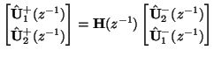
 matrix function of the unit delay, which we assume to be para-unitary (lossless) [193]. The input and output voltage waves are related by
(In applications in Chapter 5, where bidirectional delay lines are extracted from an MDKC, we will always set
to be a multiple of the
identity matrix.)
We can define instantaneous current wave vectors
 and
and
 , for
, for  , and Ohm's Law becomes, in the vector case,
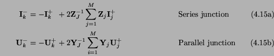
The scattering equations at a series or parallel junction of  waveguides generalize in a straightforward way to the vector case--we have
for
 , where
 is the admittance of the
  th waveguide, which must exist because
 is assumed positive definite (for passivity) [167]. The vector junction admittance and impedance are defined by
 |
 |
|
Series junction |
|
 |
 |
|
Parallel junction |
|
By virtue of the fact that they are sums of positive definite matrices, they will also be positive definite, and thus their inverses, used in the scattering equations (4.16), must exist.
Vector waveguides were explored extensively in [169] in the context of artificial reverberation. Power normalization may also be applied by scaling the wave variables by a square root of the impedance (which is non-unique) [167]. Vector junction passivity has been shown to hold in the fixed word-length case in [167].
Subsections
Next: Vector/Scalar Waveguide Coupling
Up: Digital Waveguides
Previous: Scattering Junctions
Stefan Bilbao
2002-01-22