


Next: Progressive Grid Density Doubling
Up: Doubled Grid Density Across
Previous: Corners
To demonstrate the behavior of the interface discussed above, we will simulate the parallel-plate system (4.58), assuming no losses or sources, over a square region with side-length 1, with short-circuited boundary conditions (i.e.,  ). Over a central square region with side lengths of
 (bounded by the white square in Figure 4.37), we use a mesh of doubled density with respect to the outer region, where a simple rectilinear mesh is in place. The grid spacing in the outer region is
 . We set the capacitance per unit length
  everywhere, and the inductance per unit length
  is equal to 1 in the outer region. In the inner region, it also takes the value 1, except in the interior of the black circle in Figure 4.37(radius 0.1, center at
  ,
,  ), where it rises, in a 2D raised cosine distribution, to a maximal value of
  .
.
Figure 4.37:
Simulation of a parallel-plate system, with an inductive feature surrounded by a region of doubled grid density.
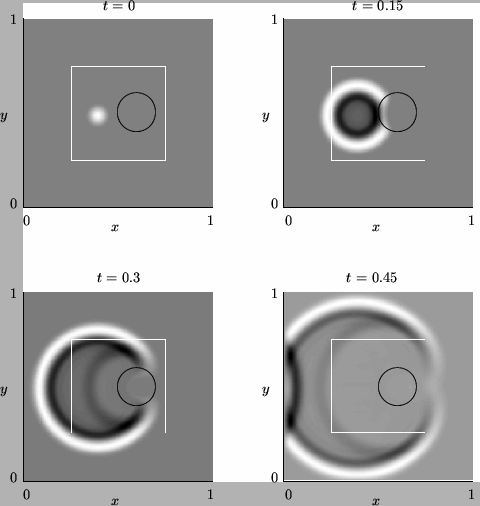 |
The initial voltage distribution takes the form of a 2D raised cosine over a circular region of radius 0.07, centered at coordinates  and . The initial voltage takes a maximum of 1, and is zero everywhere outside this circle.
The voltage distribution is shown at three successive time instants, with light and dark coloring indicating areas of positive and negative plate voltage, respectively; the plots have been normalized and interpolated for better plotting results. At time  , the voltage distribution has spread and begun to scatter from the inductive region inside the black circle. Note that the local wave speed decreases in the interior of the circle. By
  , it has progressed through the interface, with little visible numerical reflection, and by
  , the outward moving voltage distribution has reflected with inversion from the boundary at
  .
.
Next: Progressive Grid Density Doubling
Up: Doubled Grid Density Across
Previous: Corners
Stefan Bilbao
2002-01-22