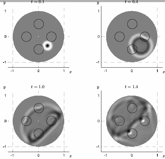
We show here a simulation of the parallel-plate problem over a circular region, radius 1, with short-circuited boundary conditions (![]() on the outer rim). The capacitance is 1 everywhere, as is the inductance except over four circular regions of radius 0.2 with centers at radius 0.5 and equally spaced around the circle (circled in black in Figure 4.32). In these smaller regions, the inductance has the form of a 2D raised cosine distribution--
on the outer rim). The capacitance is 1 everywhere, as is the inductance except over four circular regions of radius 0.2 with centers at radius 0.5 and equally spaced around the circle (circled in black in Figure 4.32). In these smaller regions, the inductance has the form of a 2D raised cosine distribution--![]() takes on a maximum value of 3 at the centers, and decreases to 1 at the edges. The initial voltage distribution is a raised 2D cosine of radius 0.15 and amplitude 1, centered at radius 0.5, directly between two of the circular regions of higher inductance. The grid spacings are
takes on a maximum value of 3 at the centers, and decreases to 1 at the edges. The initial voltage distribution is a raised 2D cosine of radius 0.15 and amplitude 1, centered at radius 0.5, directly between two of the circular regions of higher inductance. The grid spacings are
![]() and
and
![]() , and we use a radial waveguide mesh of type II.
, and we use a radial waveguide mesh of type II.
The time evolution of the voltage distribution is shown in Figure 4.32, where light- and dark-colored areas indicate regions of positive and negative voltage respectively. The plot is normalized to show voltages between ![]() (black) and 0.3 (white). We remark that the voltage distribution on this pair of plates will behave identically to the transverse velocity distribution on a clamped membrane which has regions of increased density. Interpolation has been performed for better plotting results.
(black) and 0.3 (white). We remark that the voltage distribution on this pair of plates will behave identically to the transverse velocity distribution on a clamped membrane which has regions of increased density. Interpolation has been performed for better plotting results.