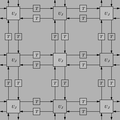
We can go further as well--if we have dropped half the junction calculations at any given time step, then we are in fact only using one of the two delay registers in any bidirectional delay line (grey or white in Figure 4.22). Thus only one delay register will be required for any waveguide. In addition, because in calculating the junction voltage at a grey junction (say), we make use only of incoming wave variables, and not the junction voltages at the white junctions, calculated one time step previously, one set of registers may be used at alternating time steps to store both the grey and white voltages.
This amounts to a factor-of-two savings in terms of both memory requirements and the operation count. We are, of course, approximating the solution at only half the mesh points at any time step, but there is no reduction in accuracy, because the separate sub-calculation which has been removed operated completely independently. (It is true, however, that we have sacrificed the higher end of the range of spatial frequencies which can be approximated without aliasing.) One additional advantage is that under this simplification, there will be no need for temporary registers (normally necessary during the scattering operation); at a given time step there is no danger of overwriting an incoming wave variable at a particular junction, because if we have just scattered there, we will not scatter there again for two time steps. The savings in terms of memory is of a factor of ![]() over the standard mesh implementation, though the reduction in the spatial frequency range should be taken into account. We note that in this implementation, each pass through the main loop in the computer program will contain two time steps worth of scattering operations. Once one has programmed a mesh a few times, the possibility of performing such a computational trick becomes obvious, and for this reason it is rather surprising that it has apparently not been explicitly mentioned in the TLM literature, even in papers specific to parallel computation [170]. We will look at grid decomposition issues in much more detail in Appendix A.
over the standard mesh implementation, though the reduction in the spatial frequency range should be taken into account. We note that in this implementation, each pass through the main loop in the computer program will contain two time steps worth of scattering operations. Once one has programmed a mesh a few times, the possibility of performing such a computational trick becomes obvious, and for this reason it is rather surprising that it has apparently not been explicitly mentioned in the TLM literature, even in papers specific to parallel computation [170]. We will look at grid decomposition issues in much more detail in Appendix A.
Such memory-sharing ideas also appeared early on in wave digital filters which use unit elements [41] and in WDF-based numerical integration schemes [131]. We note that this idea can be applied here only for the wave equation at CFL; otherwise, if we are using, for example, a type II mesh, we necessarily have unit-delay self-loops at the junctions, so that the mesh calculation can not be similarly decomposed.