 |
|
|
Continuing our discussion in Section 2.3.3, to model multi-stringed instruments, we naturally extend our model so that each digital waveguide, models a string of the instrument, with all strings attached to a scattering junction with a load bearing at the junction, representing the mass of the instrument's bridge and top-plate. Figure 19 shows a diagram of our virtual model of a multi-string instrument with all strings coupled at the bridge.
With such a model, we are able to physically model certain interactions occurring at the bridge between the strings and body of the instrument. In the case of the acoustic guitar, all the strings are coupled at the bridge such that energy transfers from one string to another through the bridge. This effect is very prominent, in that musicians change their technique to account for ``leakage'' of energy. Guitar players refer to this phenomenon as open-string noise, which typically occurs when a guitar player plays on higher strings without muting lower strings, resulting in lower strings vibrating without being plucked. This is especially problematic for musicians playing microphoned acoustic instruments which often result in unwanted feedback. For electric guitar players, when the gain of the pickups are amplified to create distortion, unwanted vibrating strings obscure the sounds of the actual strings played.
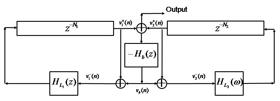
Figure 20 shows a block-diagram modeling
an instrument with two strings with a string-body scattering junction.
The digital waveguides representing each string
are simplified in that they move only in the transverse plane. As shown, energy from
one string can cause excitation of another string [27]. Furthermore,
the resulting output contains the effect of the body with the driving-point
admittance acting as a mass load at the junction. The digital waveguides used
in Figure 20 can be easily replaced with
the digital waveguide in Figure 15 such that
the output of
![]() from each digital waveguides'
transverse loop feeds into a summer into
from each digital waveguides'
transverse loop feeds into a summer into ![]() of Figure 20.
The output of
of Figure 20.
The output of ![]() is then fed back into each digital waveguide's transverse plane loop [28].
is then fed back into each digital waveguide's transverse plane loop [28].