CCRMA Documentation links: index contents overview rooms account staff about
(contents of this file: links to each section)
The CCRMA Recording Studio (Knoll 124) and Control Room (Knoll 127) comprise a traditional recording studio, massively overhauled in late 2021 into 2022 (arguably “completed” in September). Most people learn to use the CCRMA Recording Studio by taking Music 192A “Foundations of Sound Recording Technology”; access is determined by the Recording Studio Access Policy.
How to links:
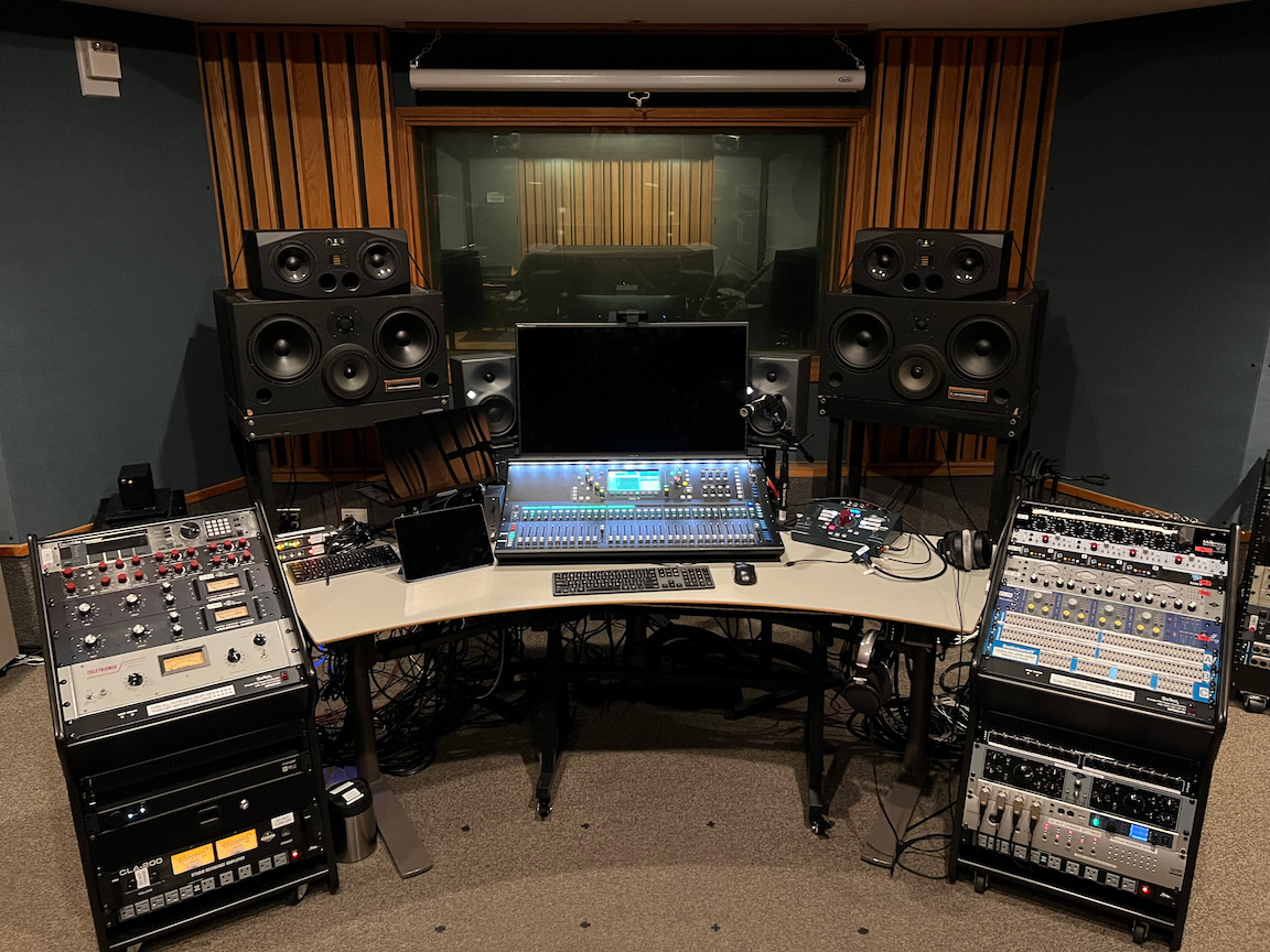
The “Recording Studio” consists of the “Live Room” (where the musicians normally perform, about 24x17 feet) and the “Control Room” (where the recording engineers normally operate the recording technology, about 20x15 feet), separated by a window. This section simply inventories the two rooms; later sections explain usage, connections, etc.
(XXX need photo(s))
Put away everything you used, for example:
CCRMA’s Recording Studio’s Control Room contains:
cmn53),
selectable on either or both KVM switches, for running a DAW etc. on a
CCRMA-maintained computerHere’s the basic way to connect to the studio for common tasks:
SQ7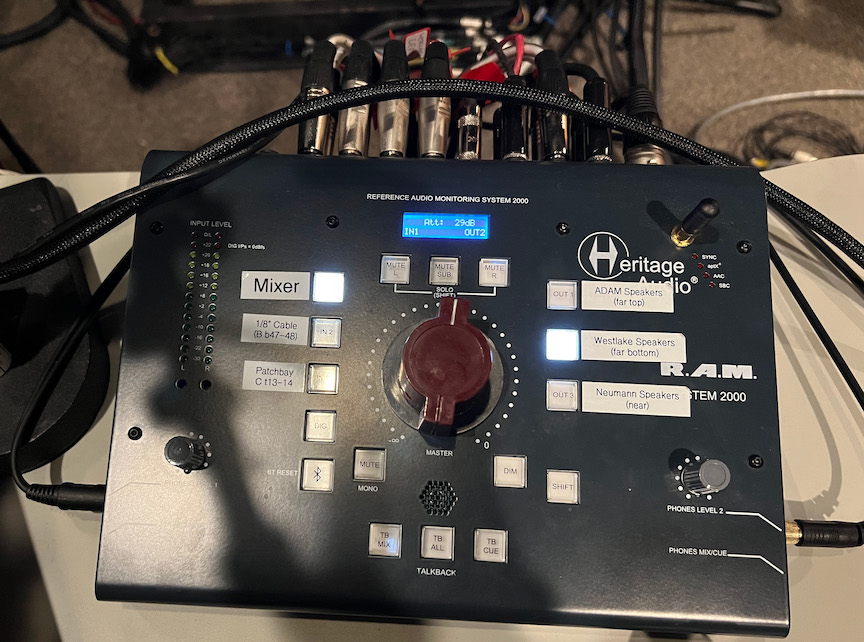
The Heritage Audio Reference Audio Monitoring System 2000 controls which stereo sound source is how loud in which of the speaker pairs.
The huge central red dial sets the gain in clicking 1 dB increments.
The labeled buttons on the left select the input source:
HERITAGE RAM 2000 as a Bluetooth
“speaker” to make a convenient lossy wireless connection to control room
sound.
The labeled buttons on the right select one stereo loudspeaker pair as the output destination:
(The vertical arrangement of the three buttons maps to the spatial arrangement of the speakers.)
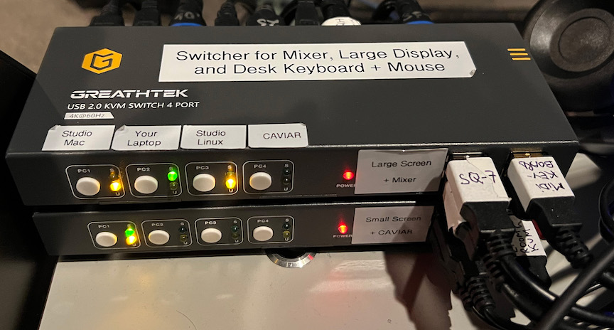
The Recording Studio contains three interconnected KVM (“Keyboard, Video, and Mouse”) switches that control access to the mixer, three video monitors, three keyboard + mouse sets, and a USB hub: two in the Control Room and a third in the Live Room. Each switch controls access to one video monitor plus various USB devices, switchable among four sources (e.g., your laptop or the Studio Mac Studio).
You connect your own laptop to the studio via any of these KVM switches.
KVM #1 (located in the control room) controls access to these switched devices:
KVM #1 connects all the above devices to any of four possible computers in the control room:
cmn10(Switching USB audio like this is partially inspired by Studio D).
KVM #2 (located in the Control Room) controls access to these switched devices:
KVM #2 connects all the above devices to any of two possible computers in the control room:
cmn10KVM #3 (located in the Live Room) controls access to these switched devices:
KVM #3 connects all the above devices to any of four possible computers:
To assign a mix (like an Aux send)
There are 24 channels of high-quality mic preamps:
| # | Preamp |
|---|---|
| 1-8 | Millennia HV-3D (manual) |
| 9-12 | Neve 5024 (manufacturer’s page) |
| 13-16 | API 3124+ (predecessor to their 3124V) |
| 17-20 | Universal Audio 4-710d “Tone-Blending” (*) (manual) |
| 21-24 | Focusrite ISA 428 Mkii (manufacturer’s page) |
These are wired between the live room’s “Jupiter” stage box and the mixer’s analog inputs 1-24 (where the already-preamplified signal will get a tiny bit more coloration from the additional gain stage of the mixer’s preamps). By default stage box inputs 1-24 go via mic preamp channels 1-24 (per the list above) to mixer input channels 1-24, but everything can be rerouted through the patch bay.
(*) Beware that the US 4-710d preamp is capable of strongly coloring a mic signal when overdriving the tubes. For a clean sound, keep the XXX in the XXX.
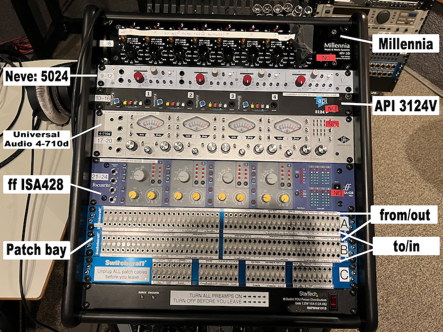
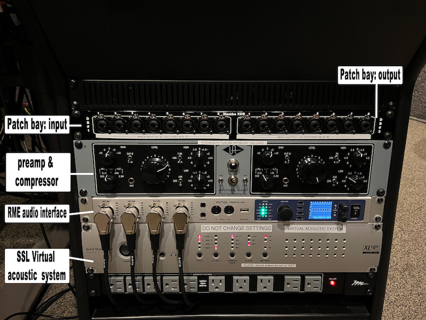
The patch bay (wikipedia) provides great flexibility in re-routing analog audio signals while also providing a default set of “normal” connections.
To return to all default signal connections, simply remove all cables from the front of the patch bay.
In general, a patch bay has connections on the front (the “points” where users can patch and repatch) and on the back (permanent connections with specific inputs and outputs of specific audio equipment). These come in top/bottom pairs, i.e., the front of each patch bay has two horizontal rows of points.
By convention, signals coming from equipment’s outputs connect to the top of patch bay pairs, while signals going to equipment’s inputs connect to the bottom, as if gravity were helping signals tend to flow down from the top row to the bottom row. (Actually the notion of “to” and “from” is more of a metaphor about your patching intentions: the patch bay really just creates direct electrical connections among whatever is plugged into it, with no inherent direction; it would not be wrong (though confusing) to say that the patch bay connects “to” all the various equipment. Also terminology can be confusing when mixing up the equipment’s point of view versus the patch bay’s point of view, e.g., an “output” “from” the patch bay going “to” a preamp “input”. We recommend thinking in terms such as “using the patch bay to connect this microphone’s output to that preamp input.”)
The main thing to avoid is patching an output to another output. An “output” on a piece of gear means that it is “trying” to put a certain time-varying voltage (between the “signal” and “ground” connections) by pumping out as much current as necessary to drive whatever impedence it’s plugged into. Bad things happen when two or more different pieces of equipment try to do that at the same time to the same point in the circuit.
Three possible normalization modes determine how plugging into the front affects a possible default connection between the two signals plugged into the back:
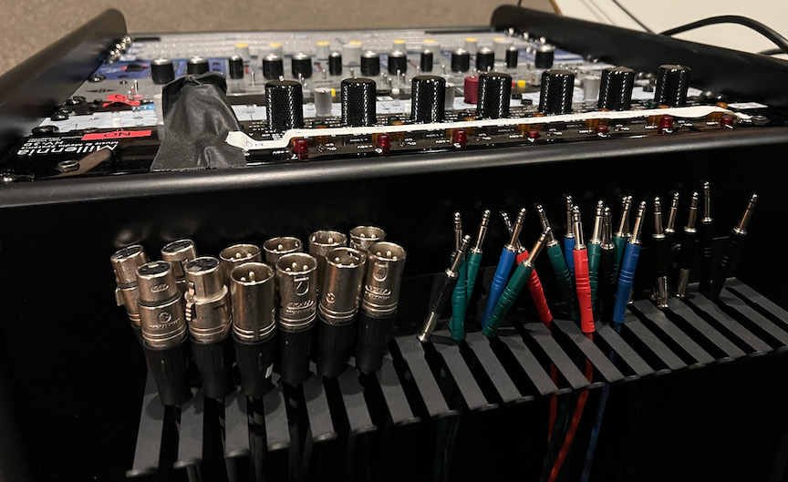
All patch bays in the CCRMA recording studio use “TT” (aka “Bantam”) connectors for the front points. These appear quite similar to 1/4” (7mm) TRS audio, but are slightly smaller and with a different shape that tends to avoid clicks when making and breaking connections. (On the rear are DB25 aka D-sub connectors each plugged into an 8-channel snake.) A small assortment of adapter cables between TT and either XLR or 1/4” TRS allow you to plug equipment directly into the front of the patch bays:
Naming convention: The three patch bays are simply
A, B, and C. Each
consists of a good number of “slots” numbered left-to-right from
1 to 48. Each slot consists of two points:
Upper and Lower. So the name of a
particular front-facing patch bay point will be of the form
B23U, in this case meaning “Patchbay B, slot 23, upper
point.”
Patch bay “A” is a Switchcraft StudioPatch 9625, with 96 points and therefore 48 slots.
Patch bay “B” is the same model as “A”.
Patch bay “C” is smaller than “A” or “B”.
CCRMA maintains a desktop Macintosh computer in the Control Room, primarily for recording and mixing.
You can log in with your CCRMA user account, which will load your home directory (including Desktop, Documents, etc.) remotely over the network. Don’t try to record or play back audio to this networked disk; instead use a “local” drive physically plugged into the machine.
The best practice is to bring your own and plug it into the machine via USB.
Otherwise you can use our local disks. Someday they will be backed up. Someday we will delete your files.
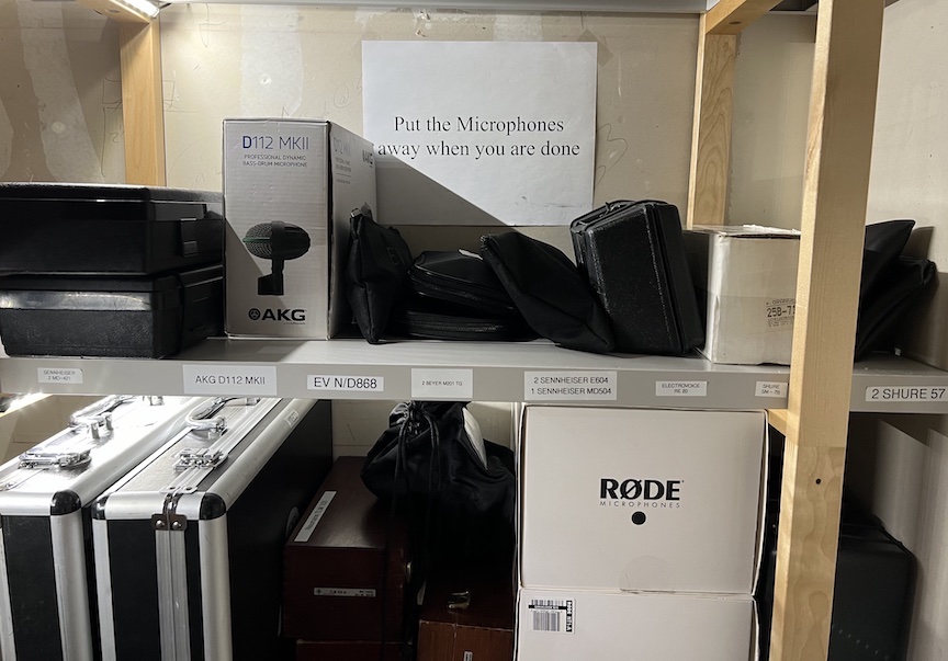
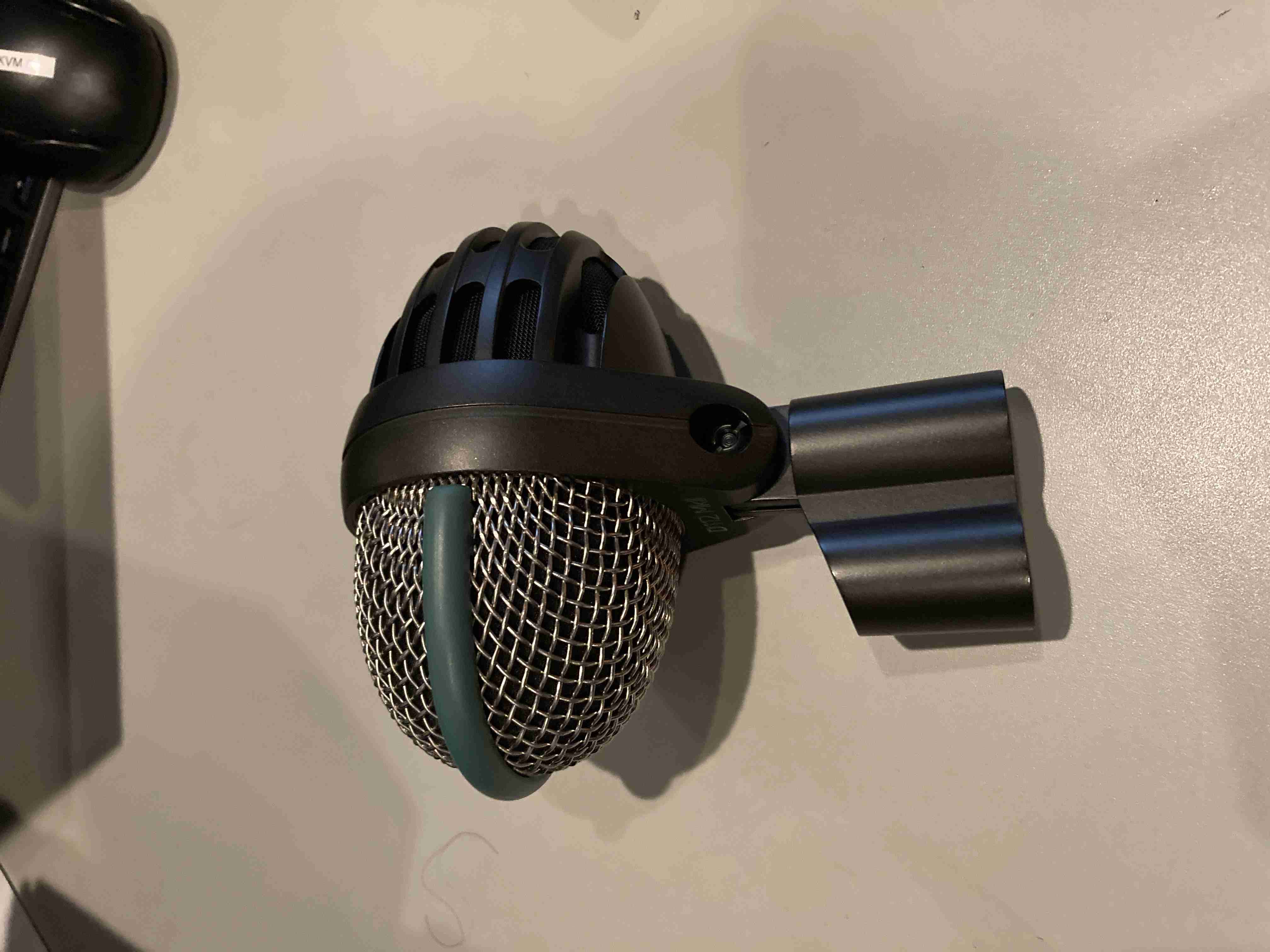
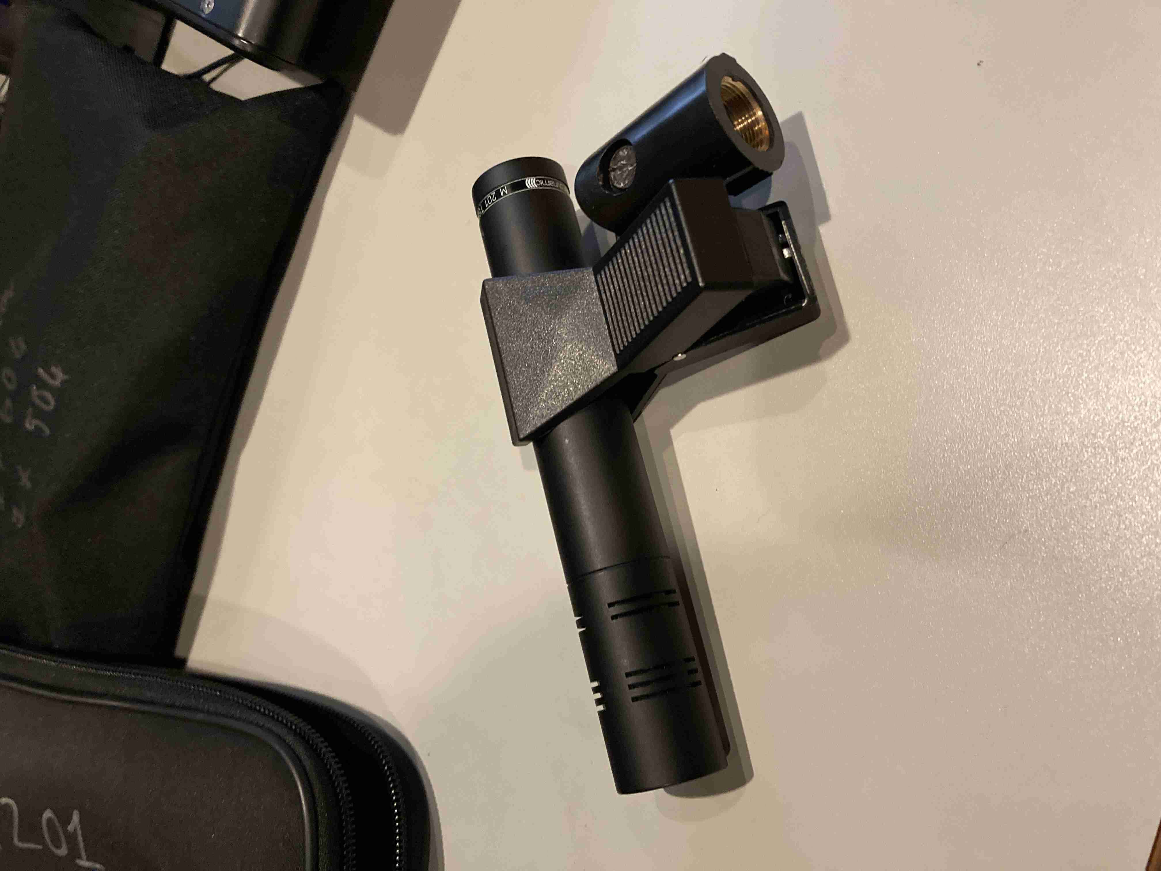
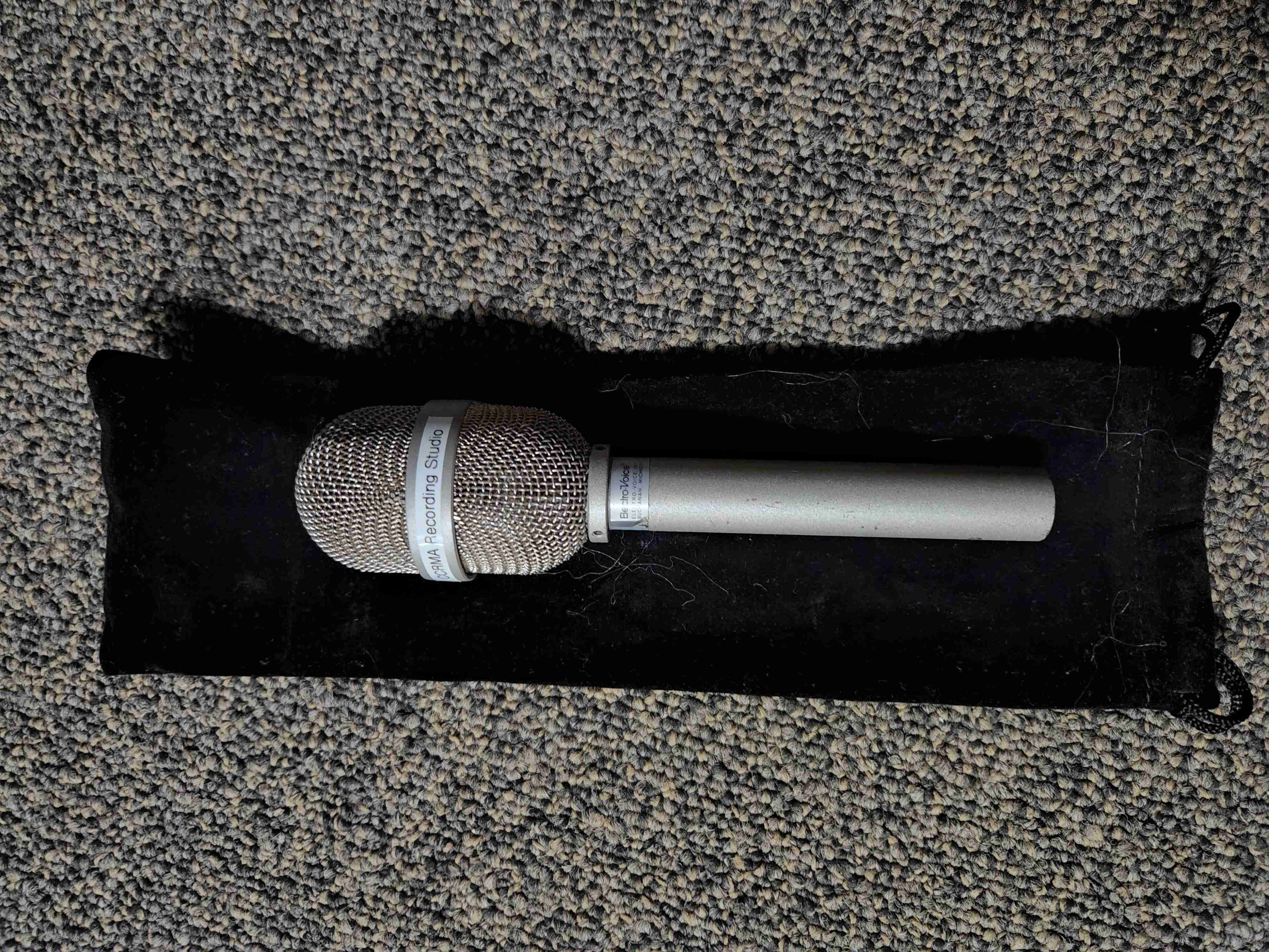
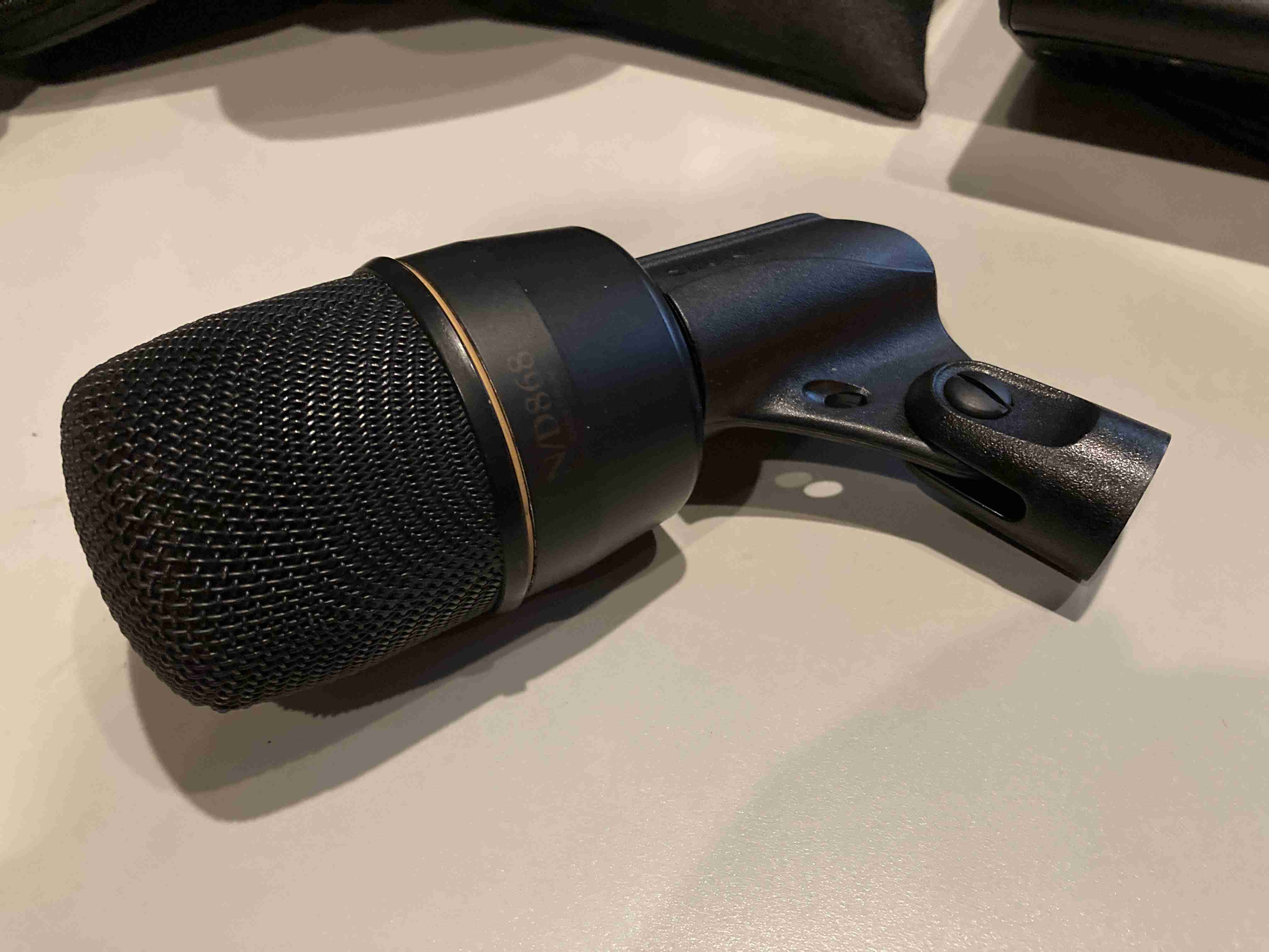
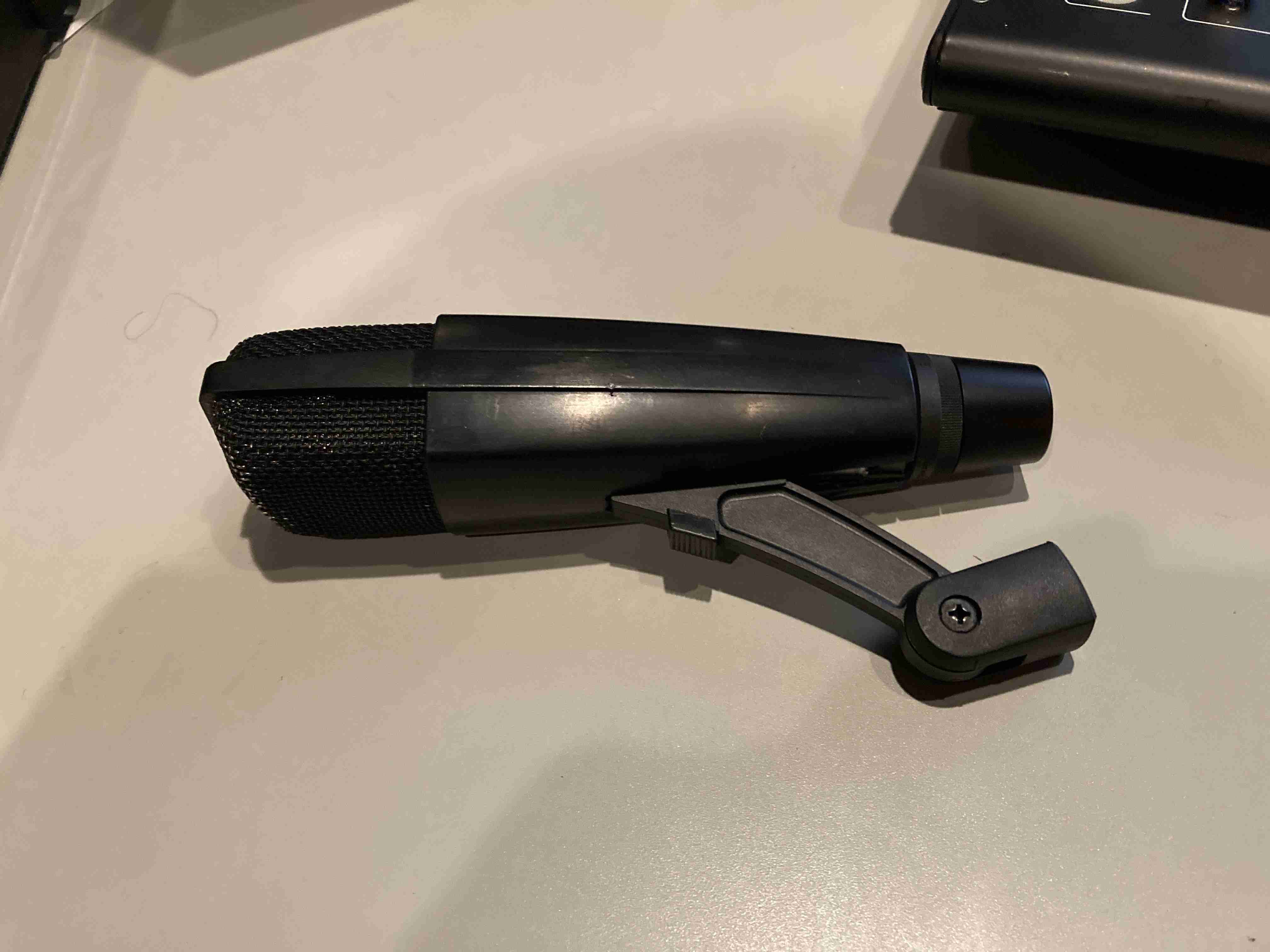
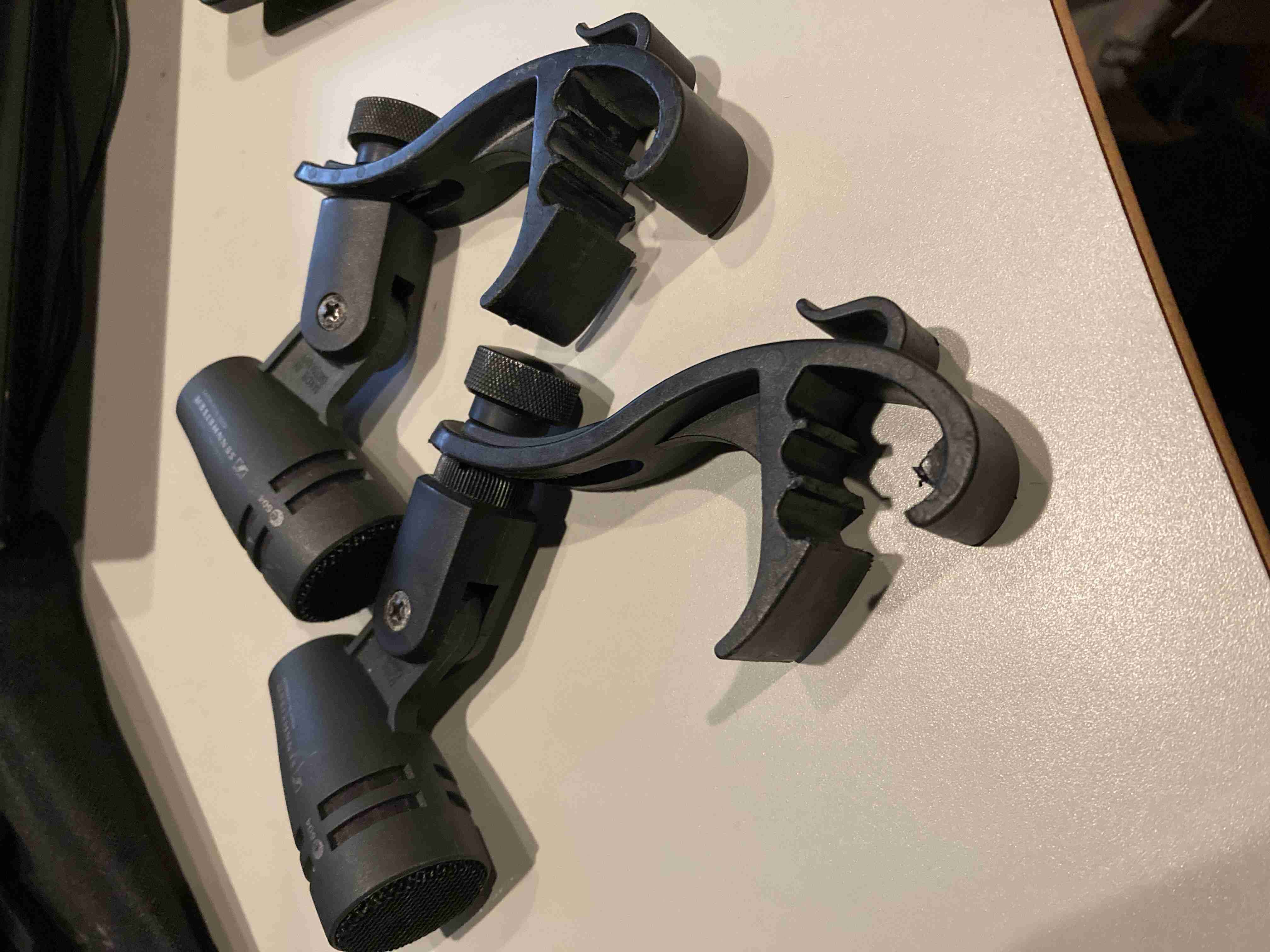
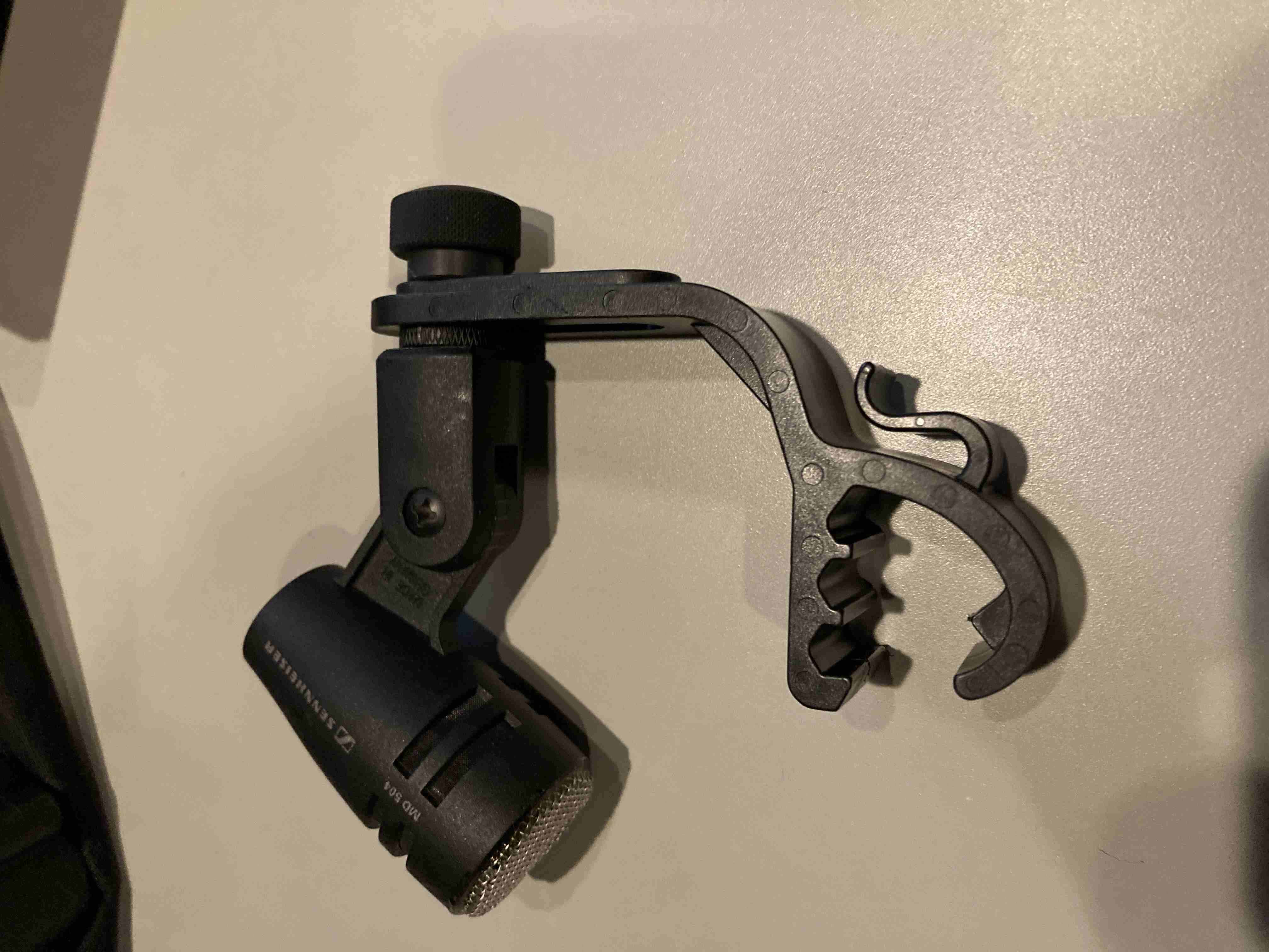
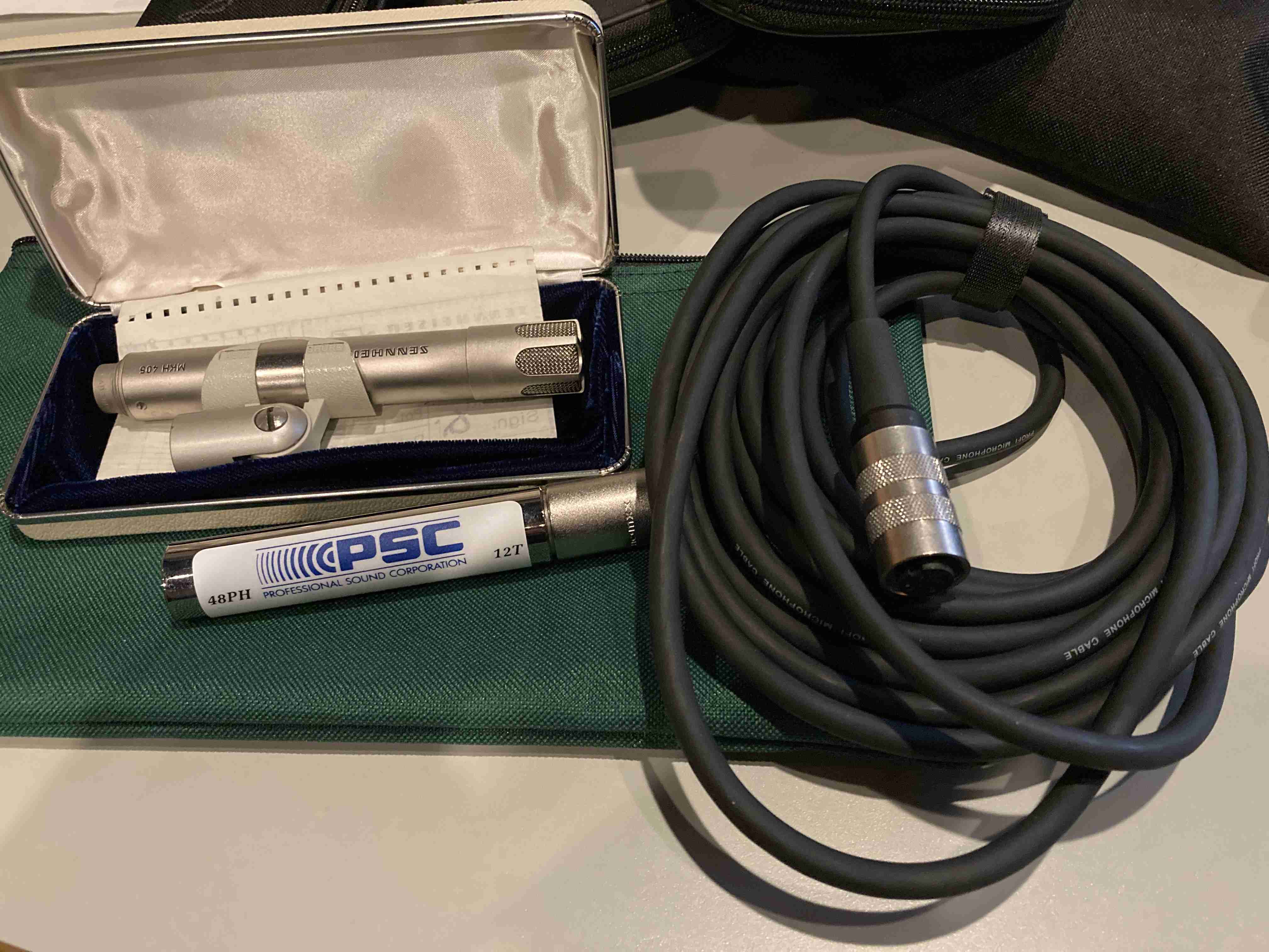
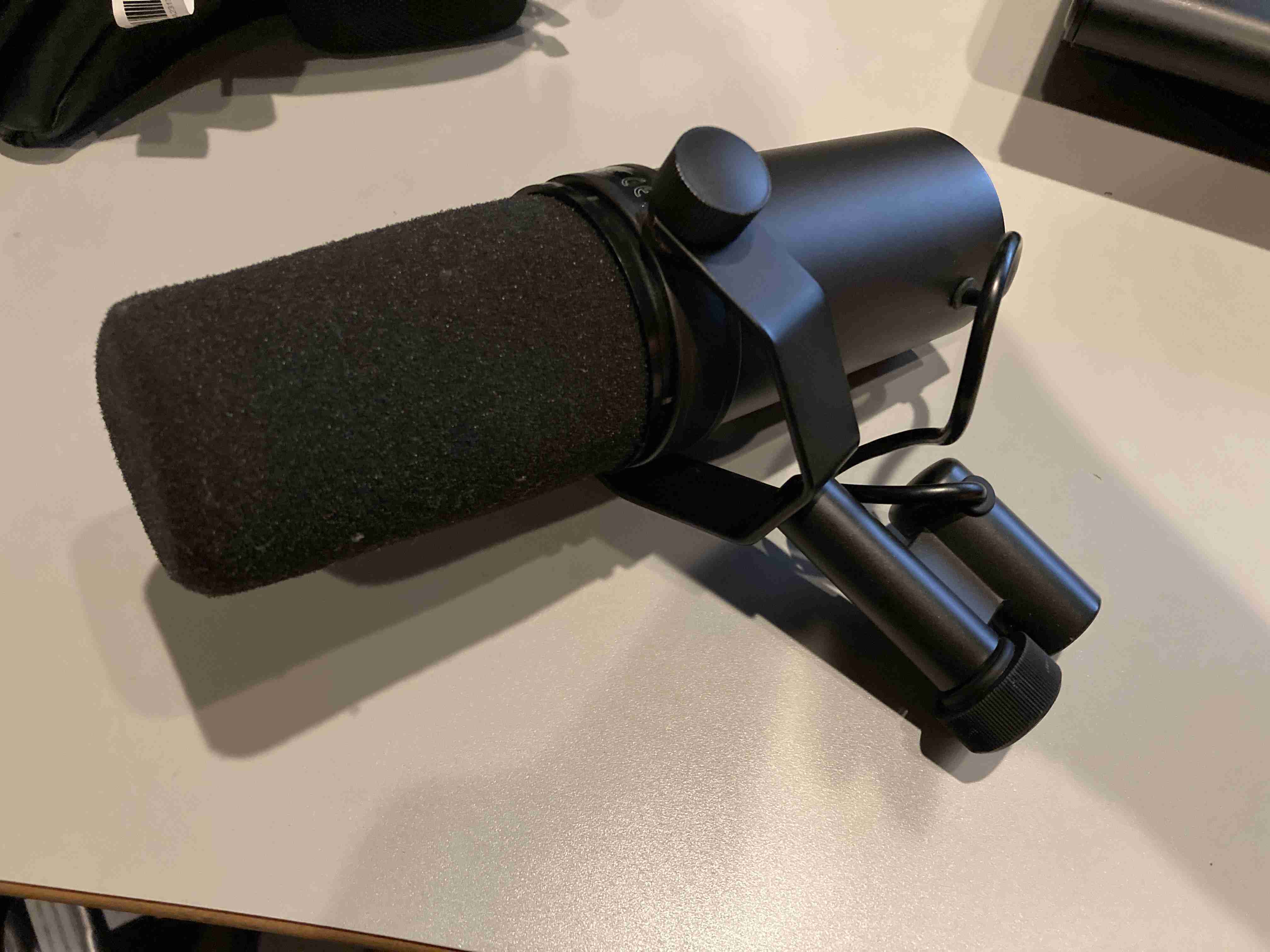
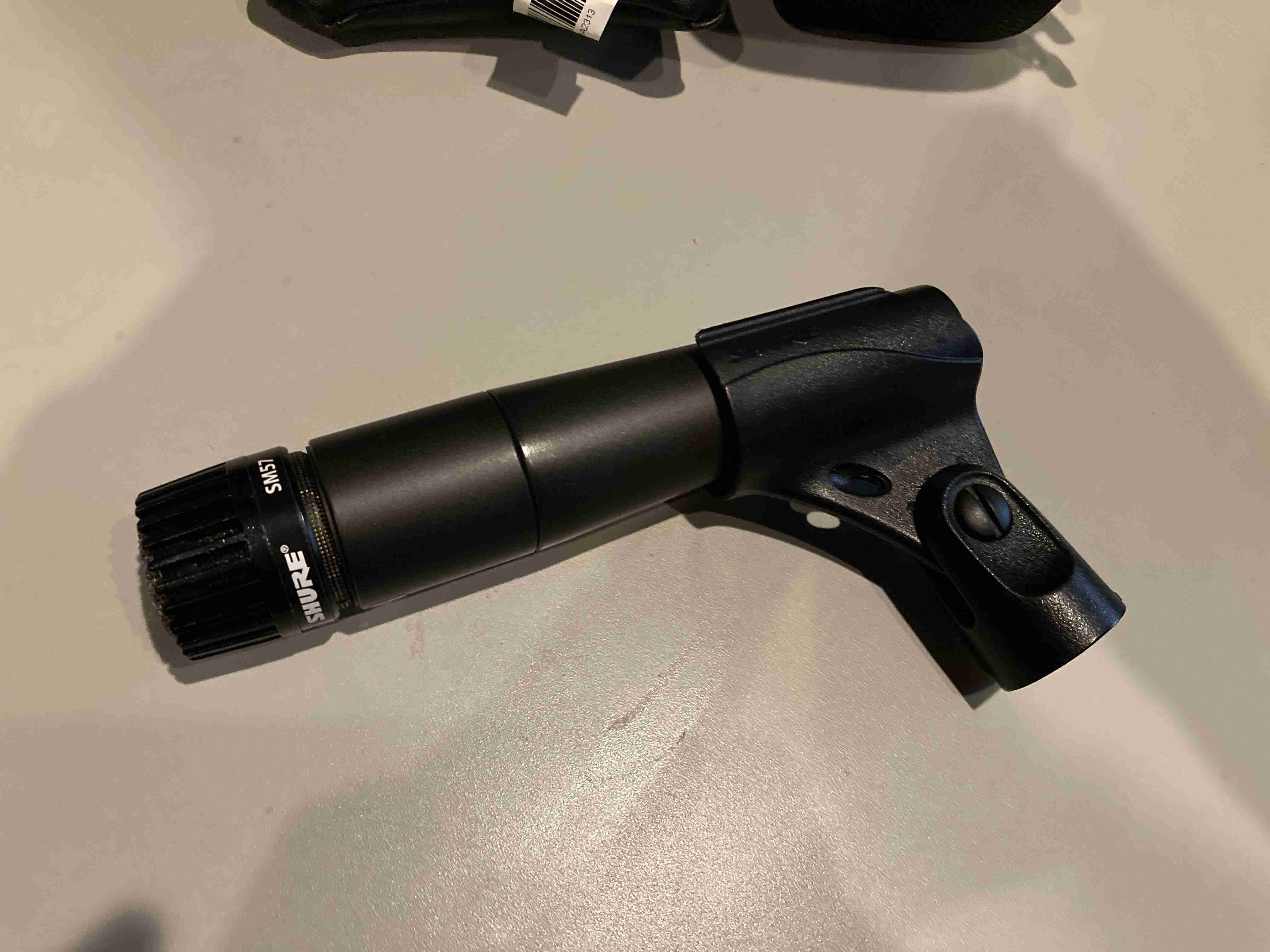
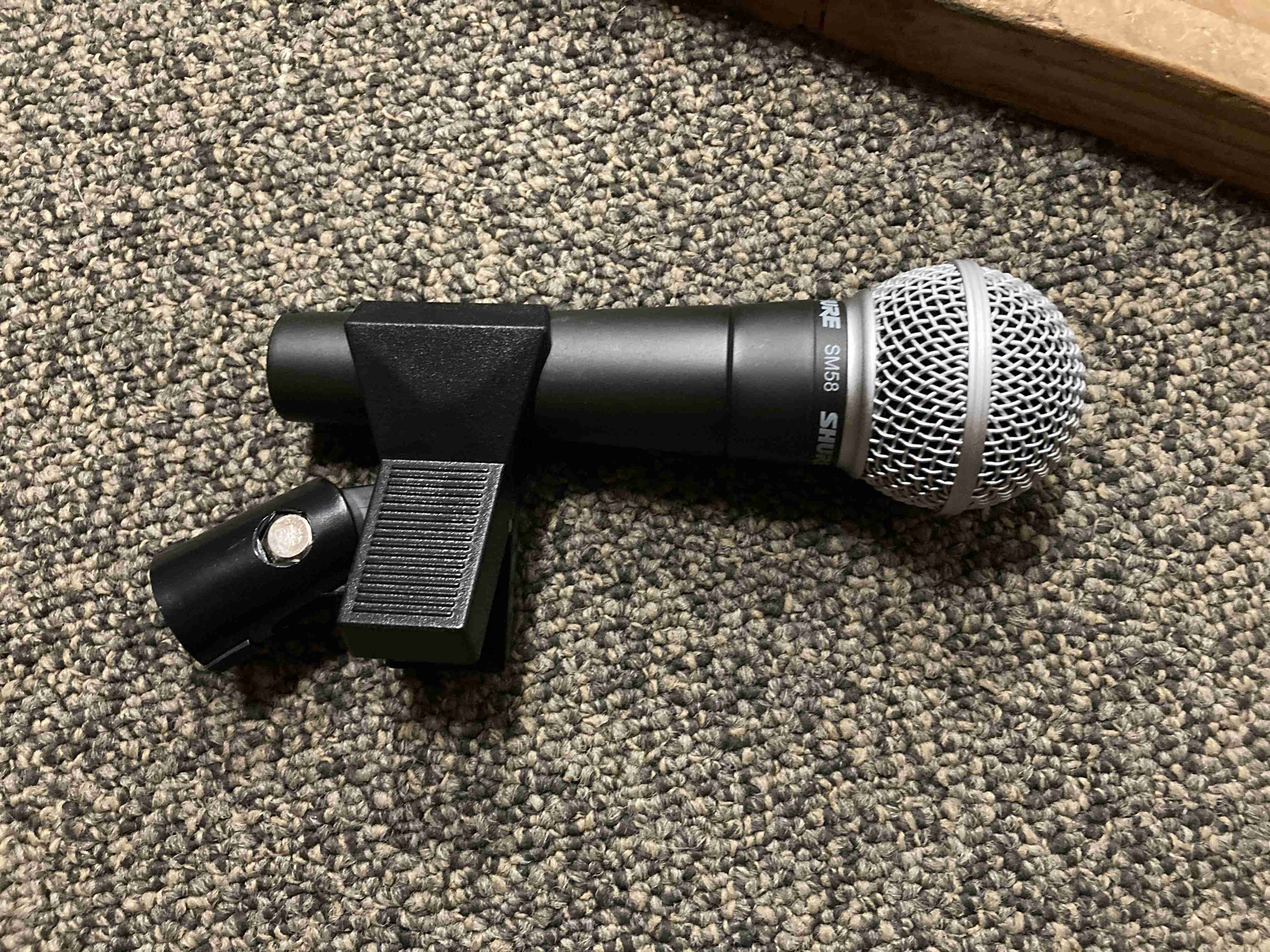
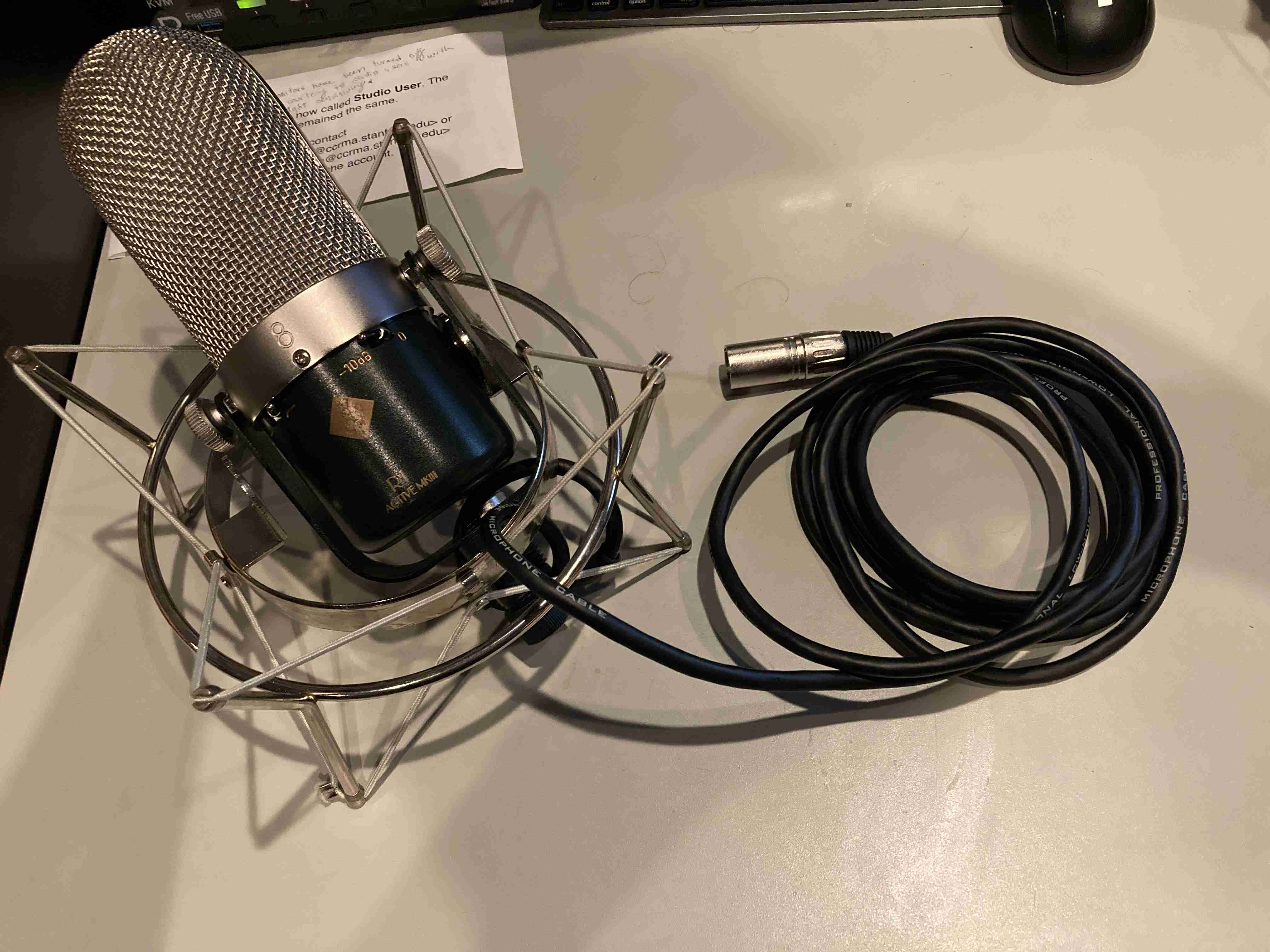
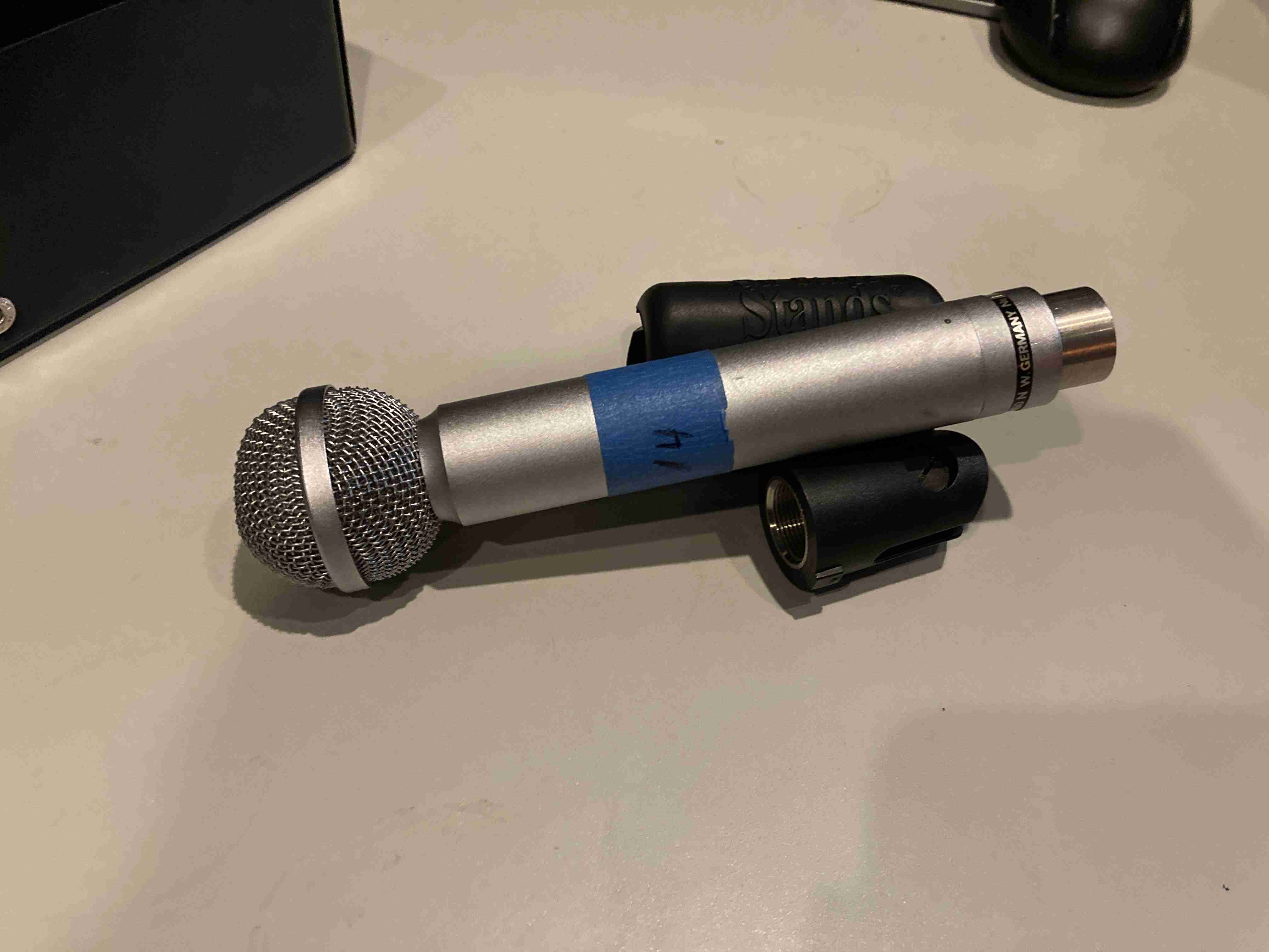
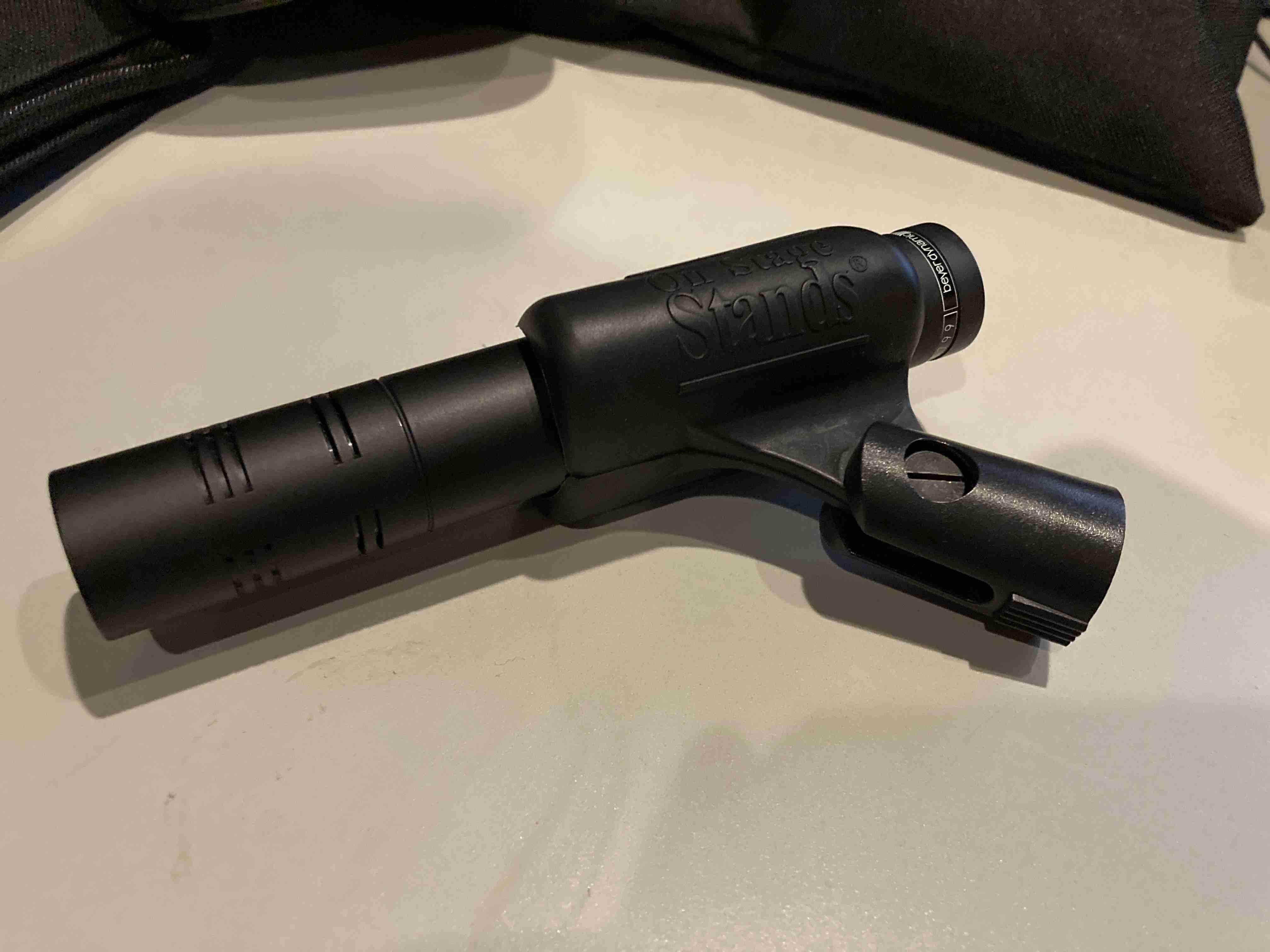
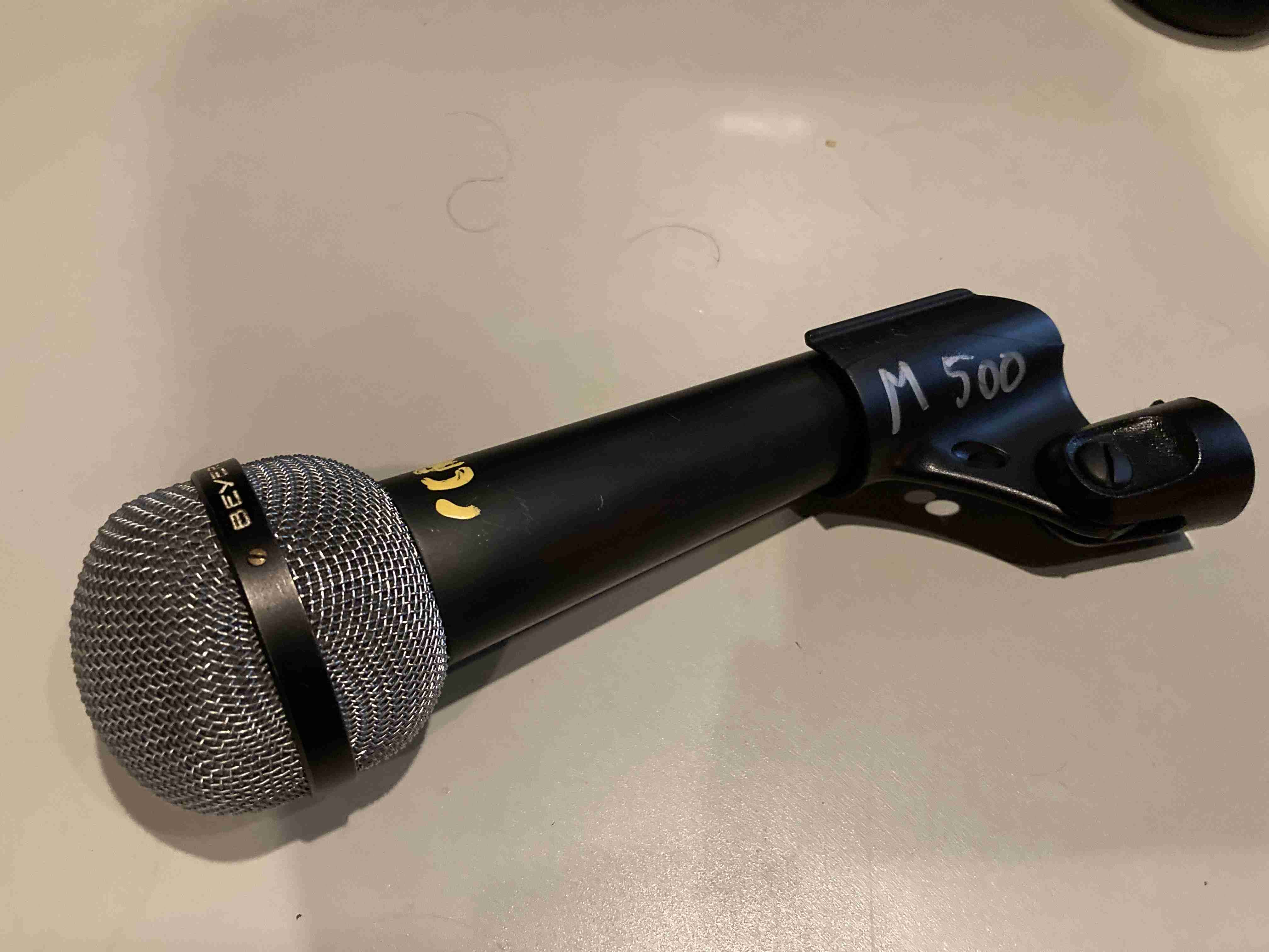
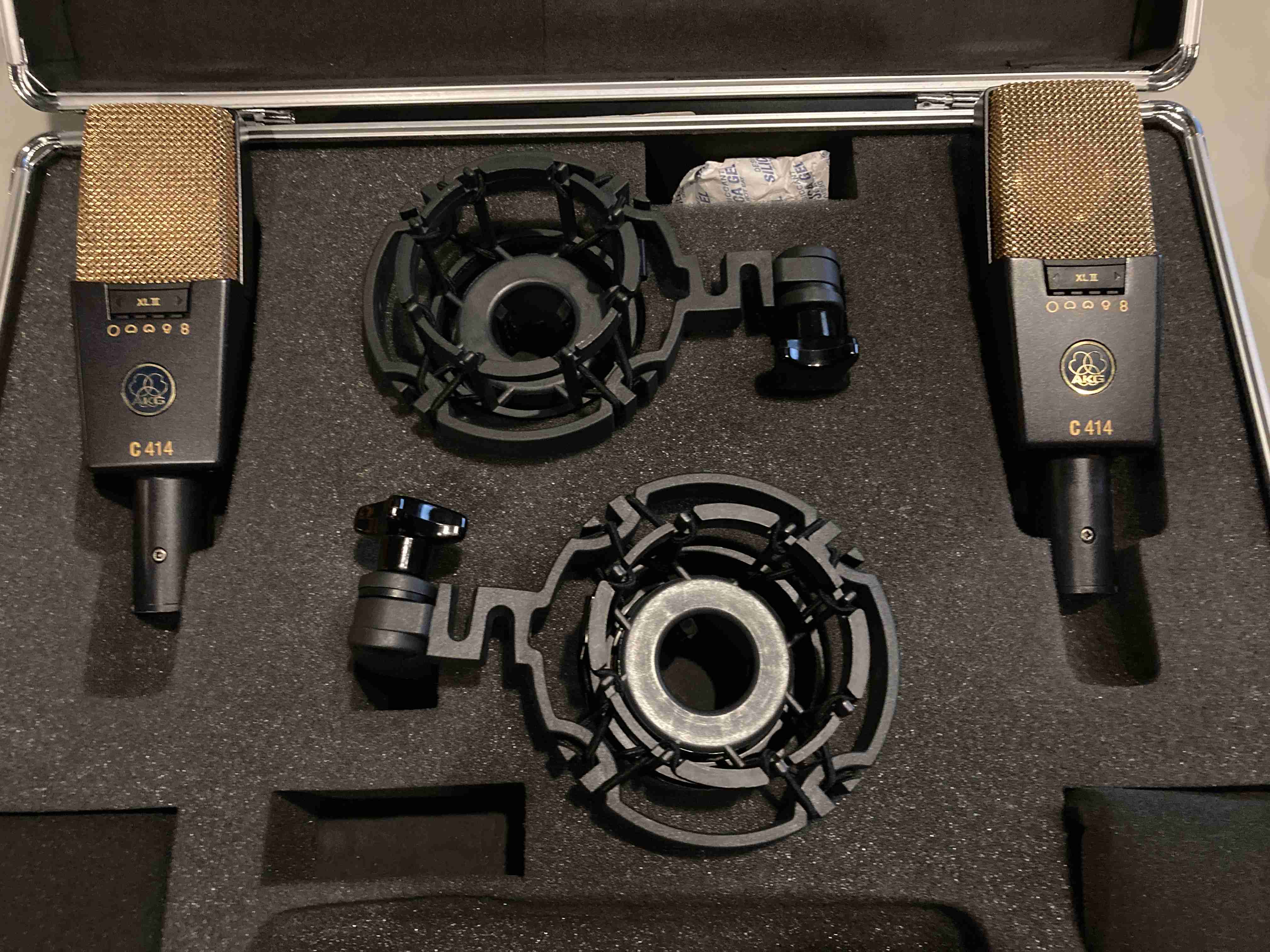
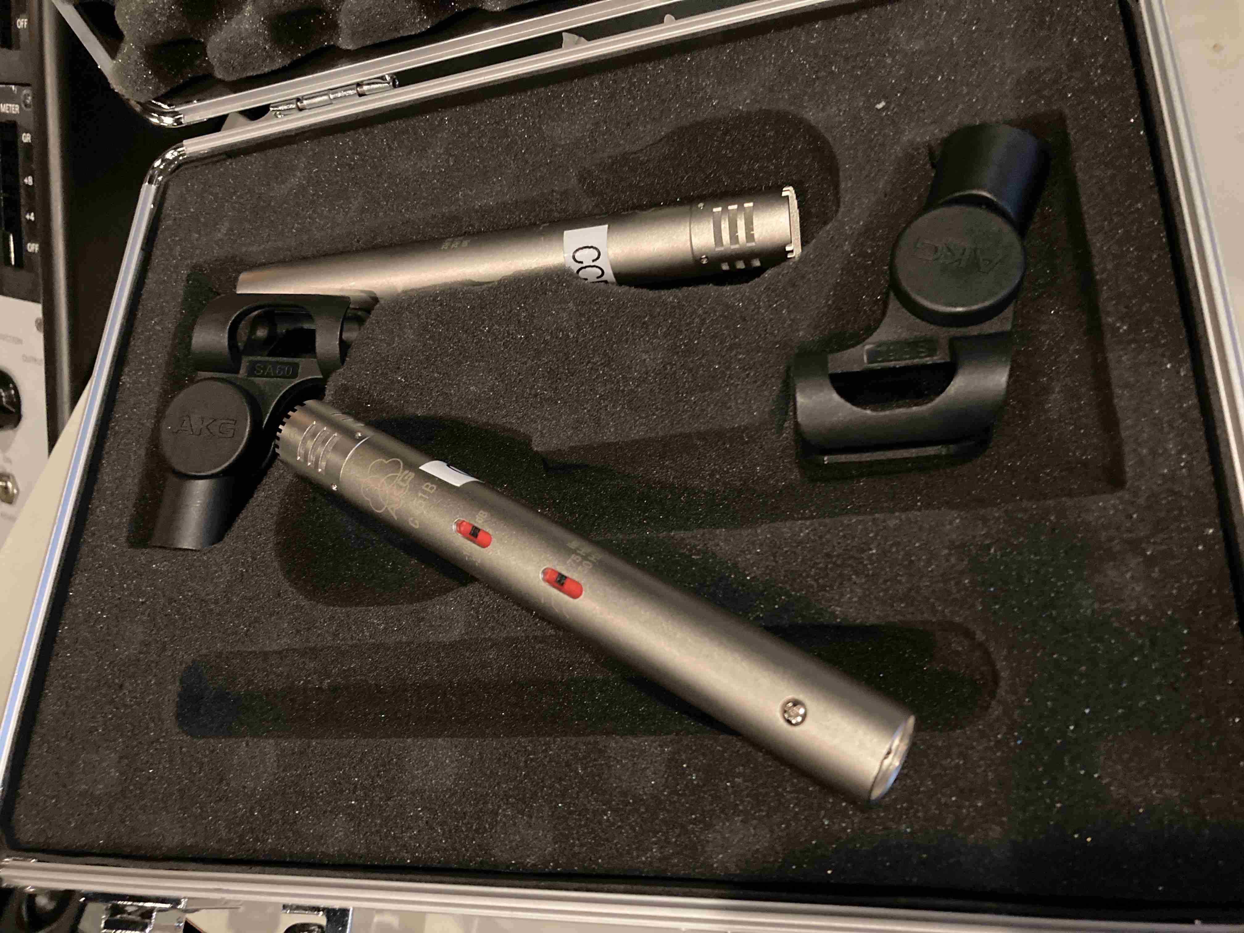
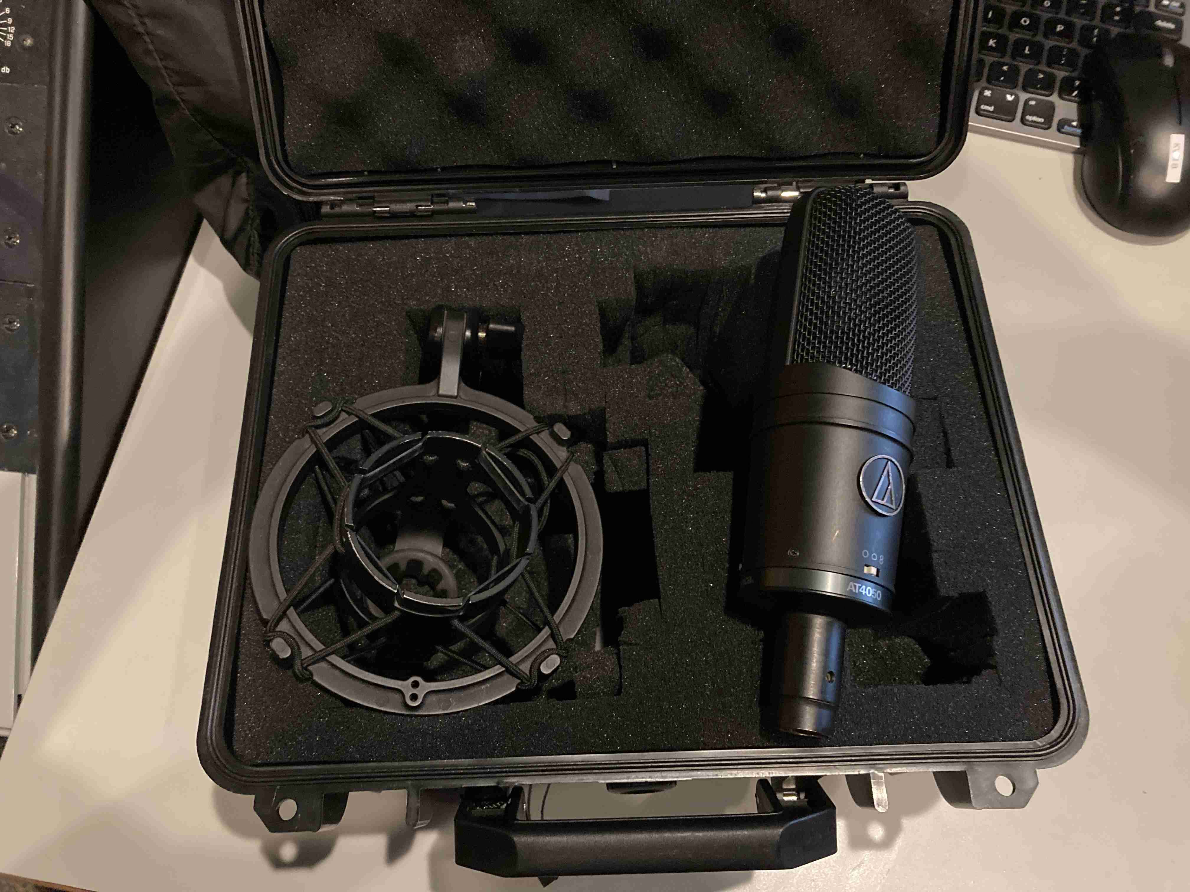
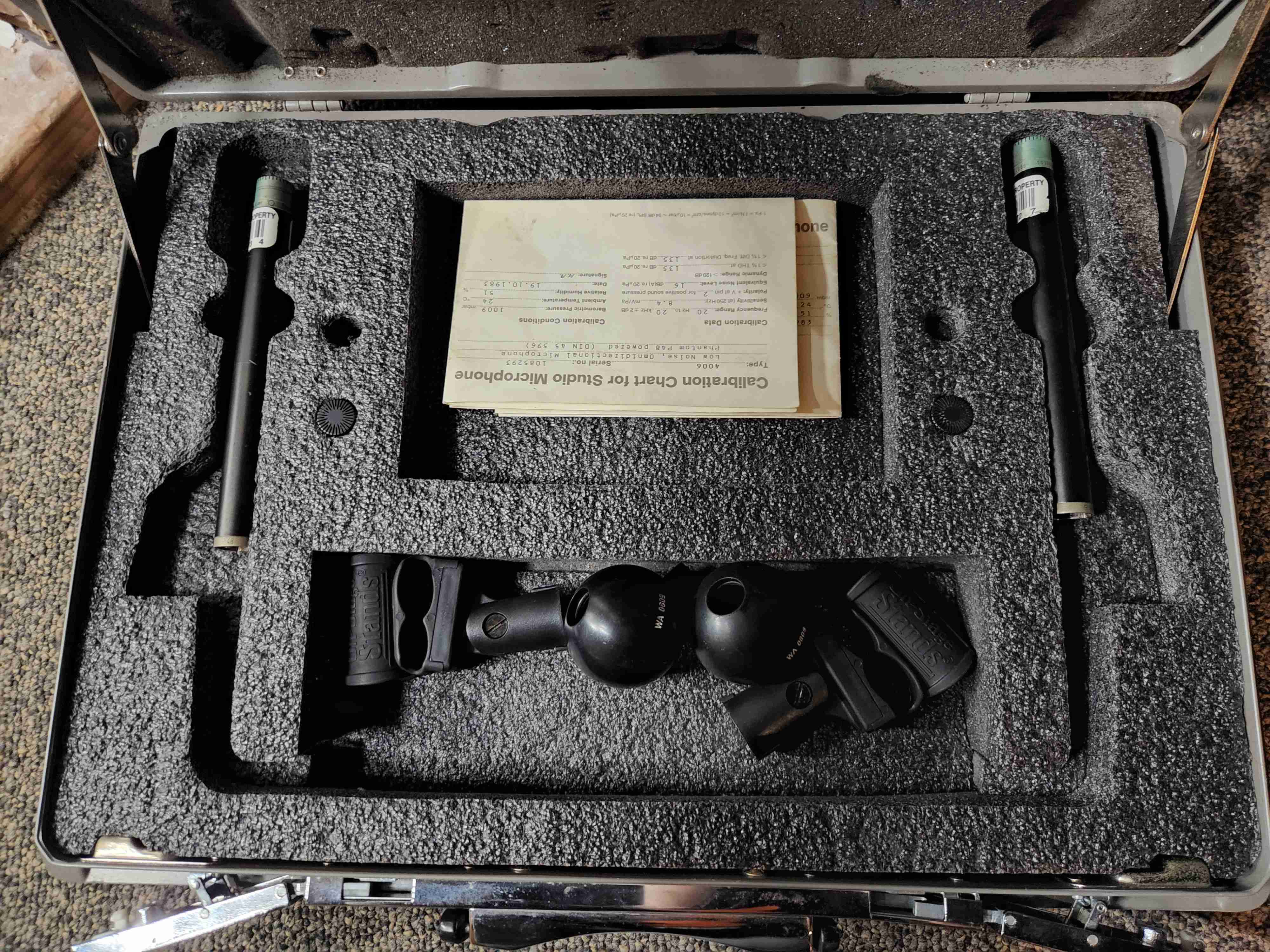
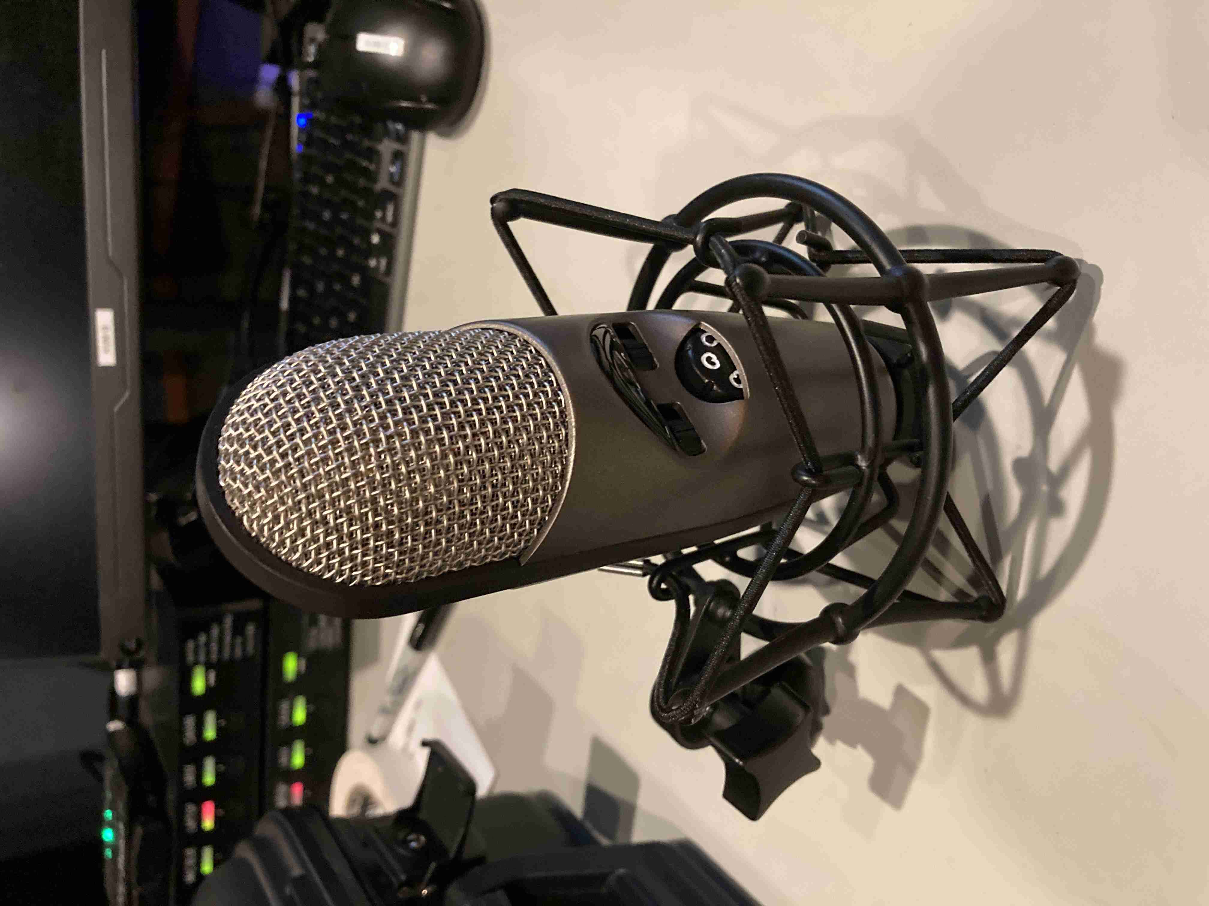
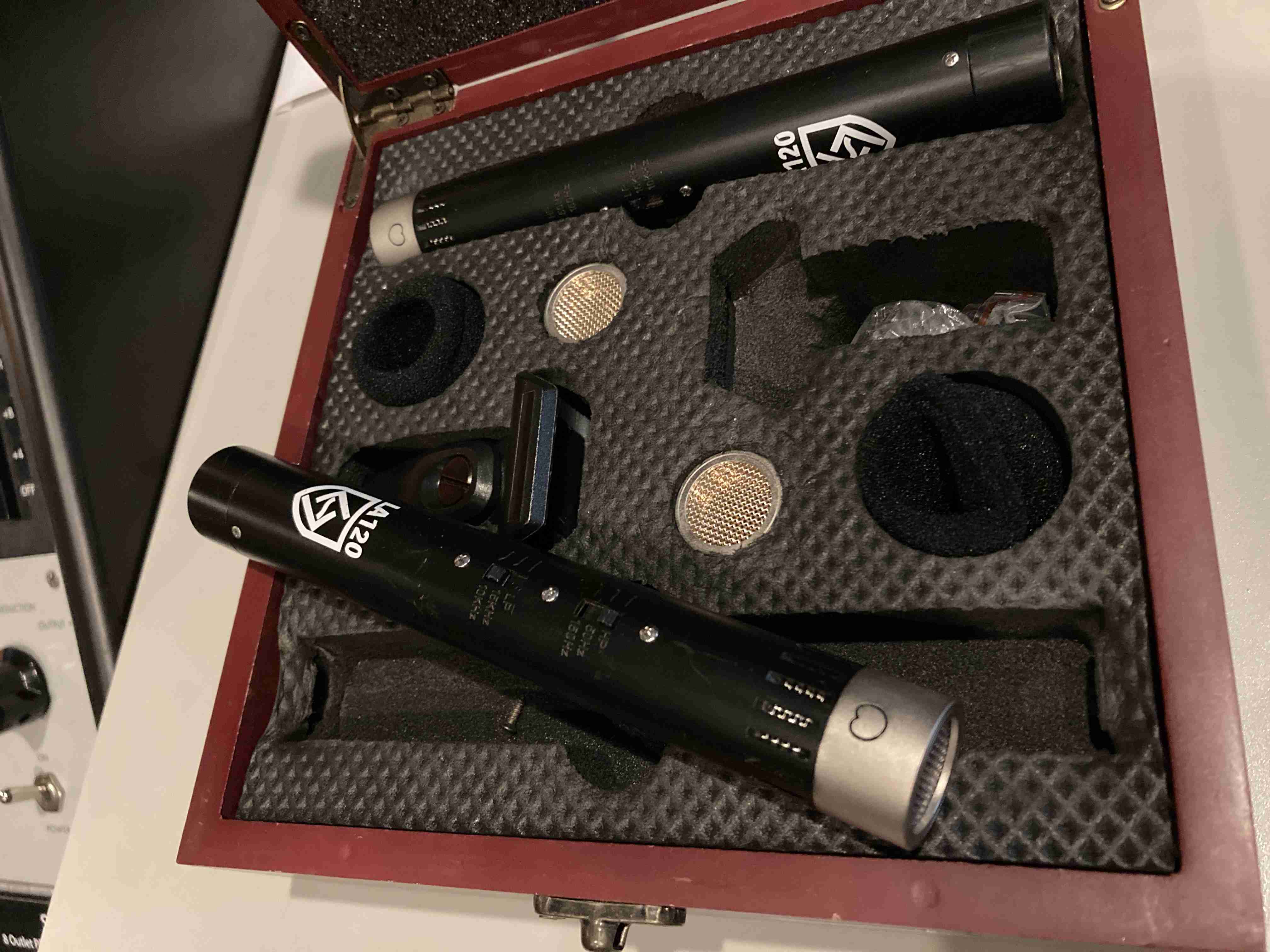
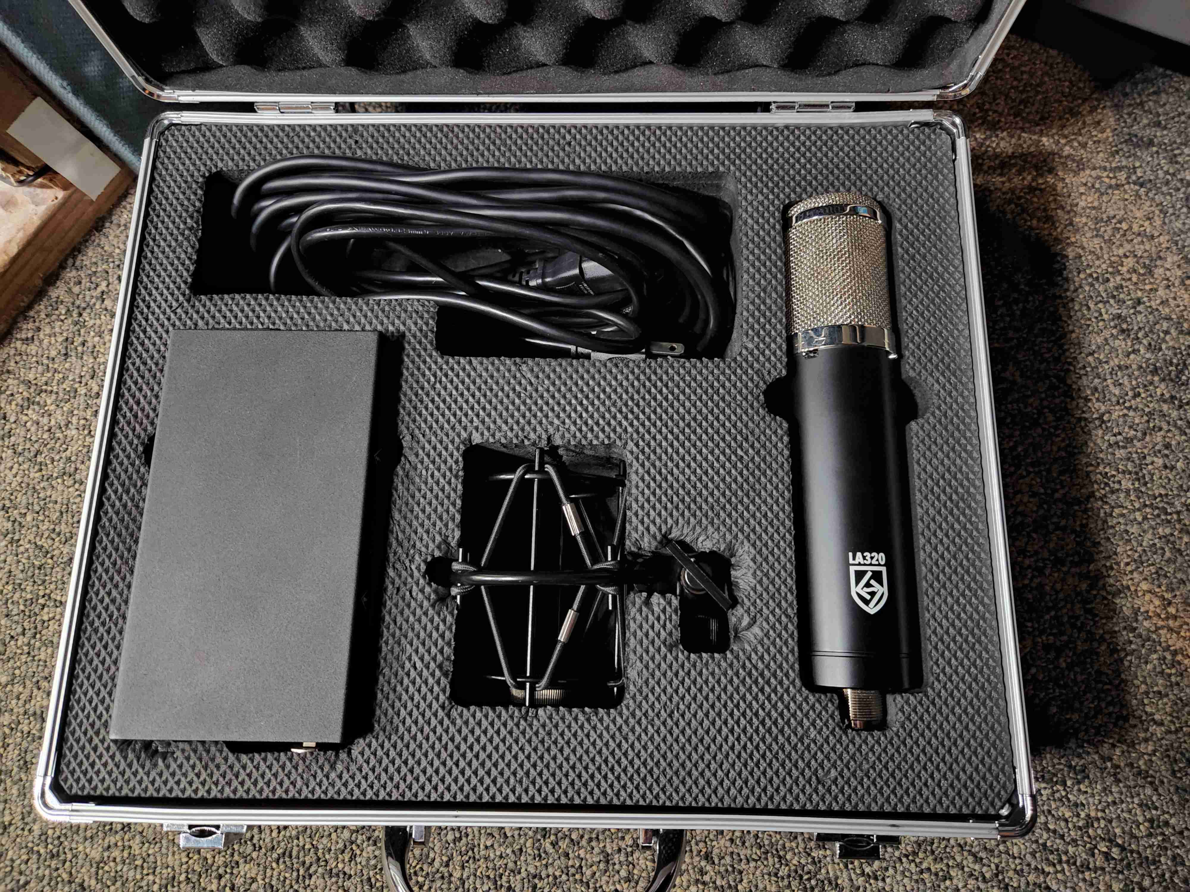
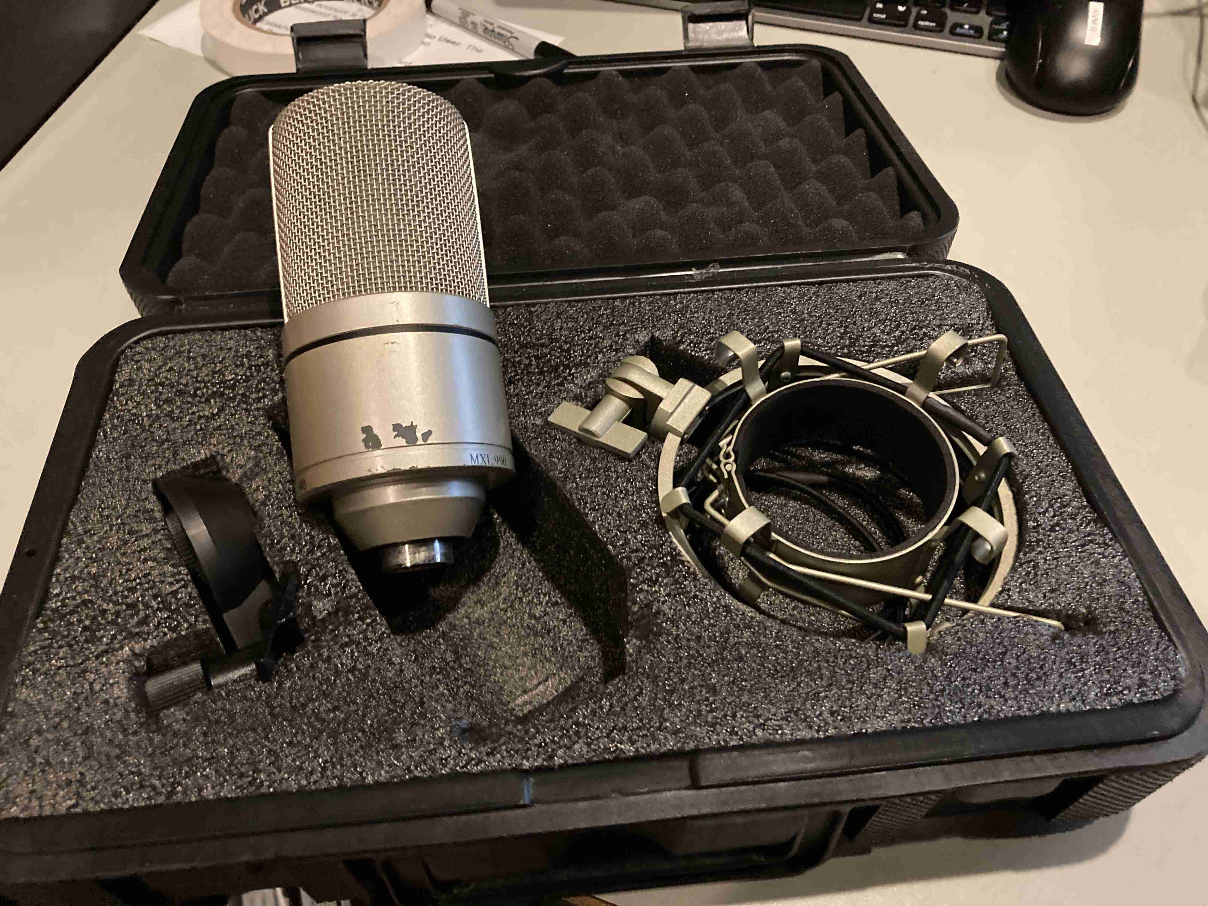
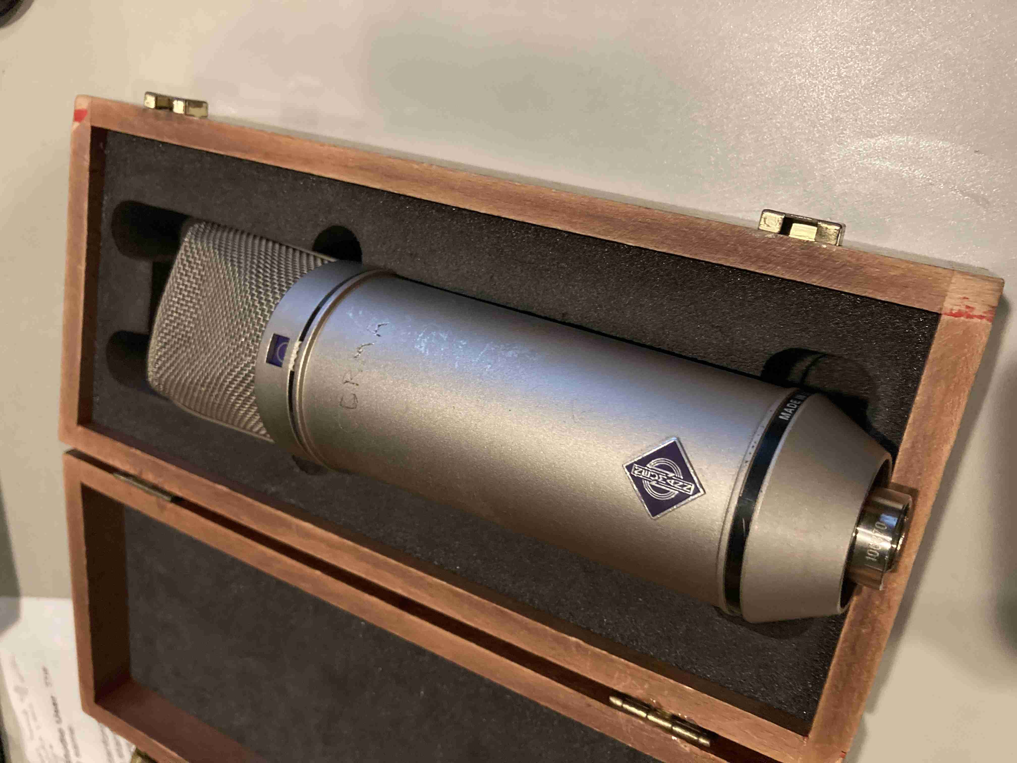
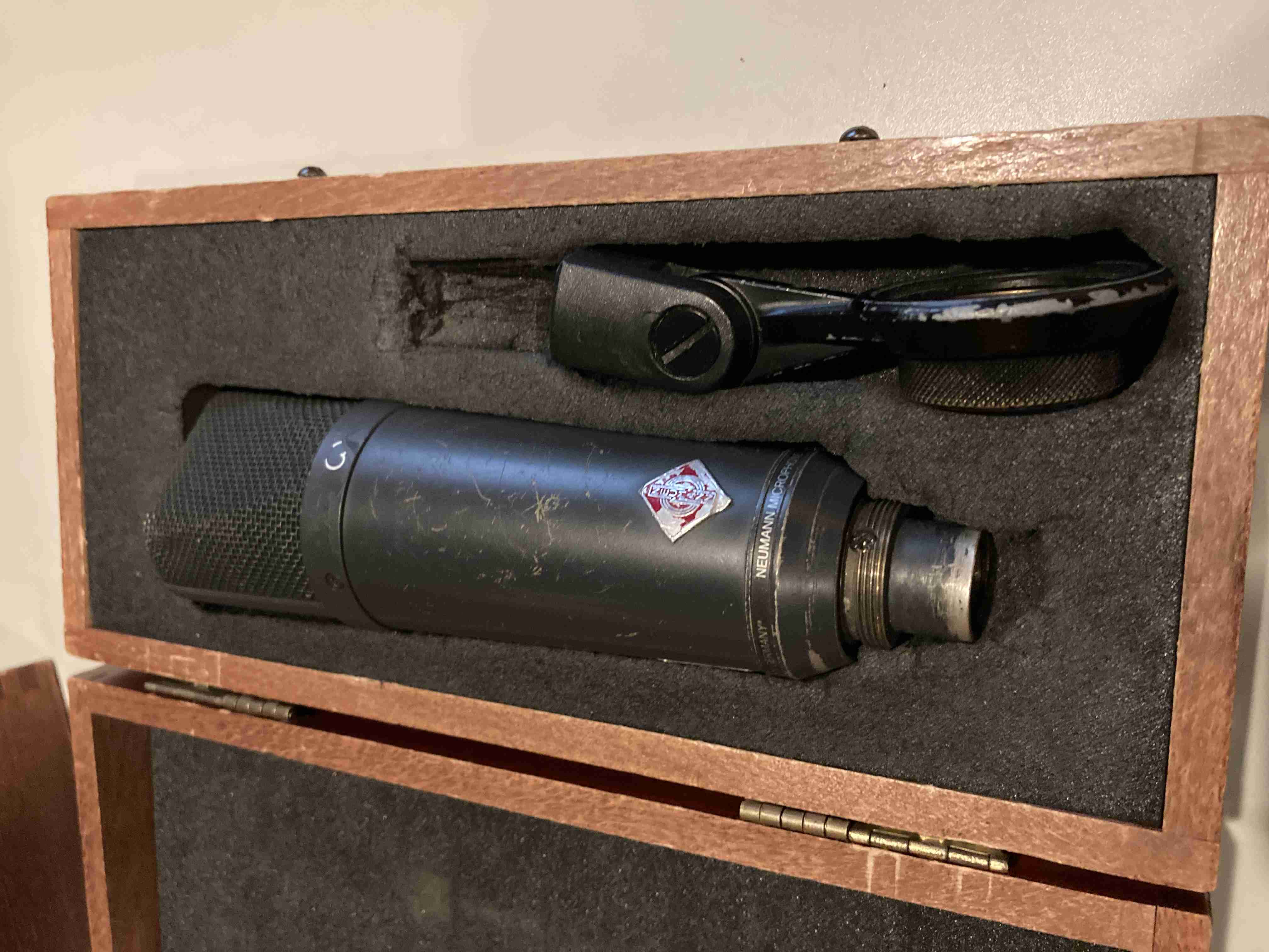
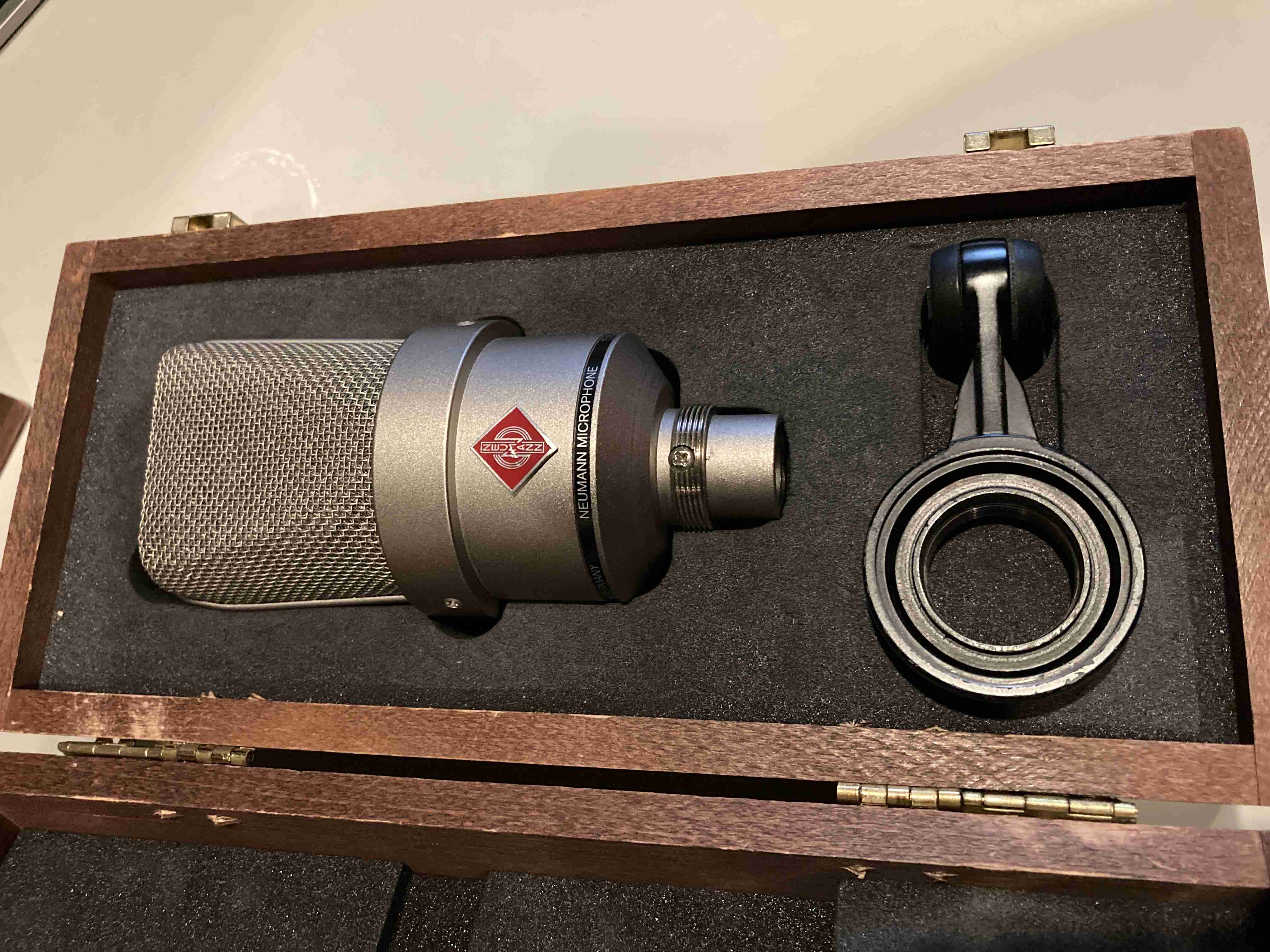
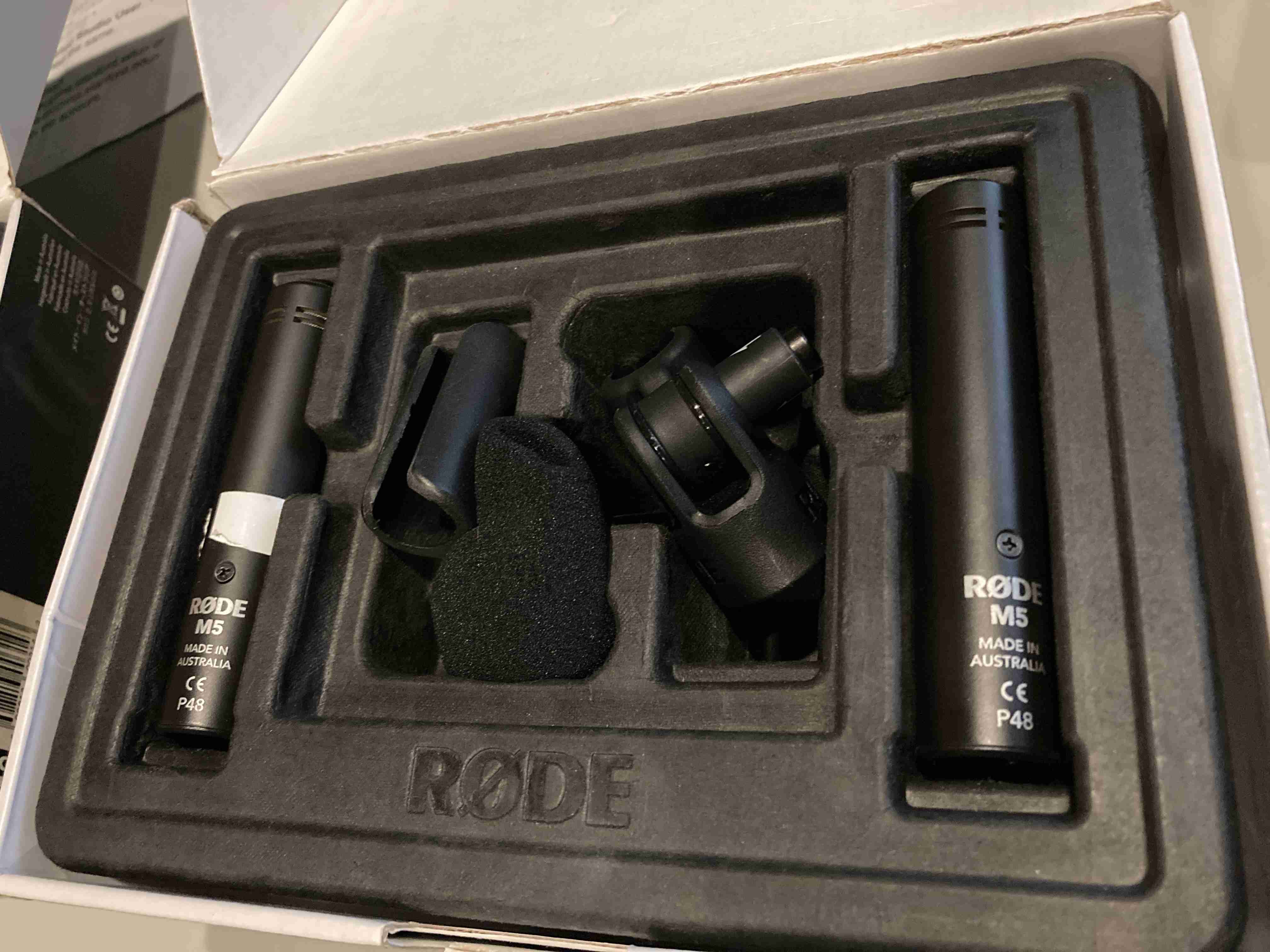
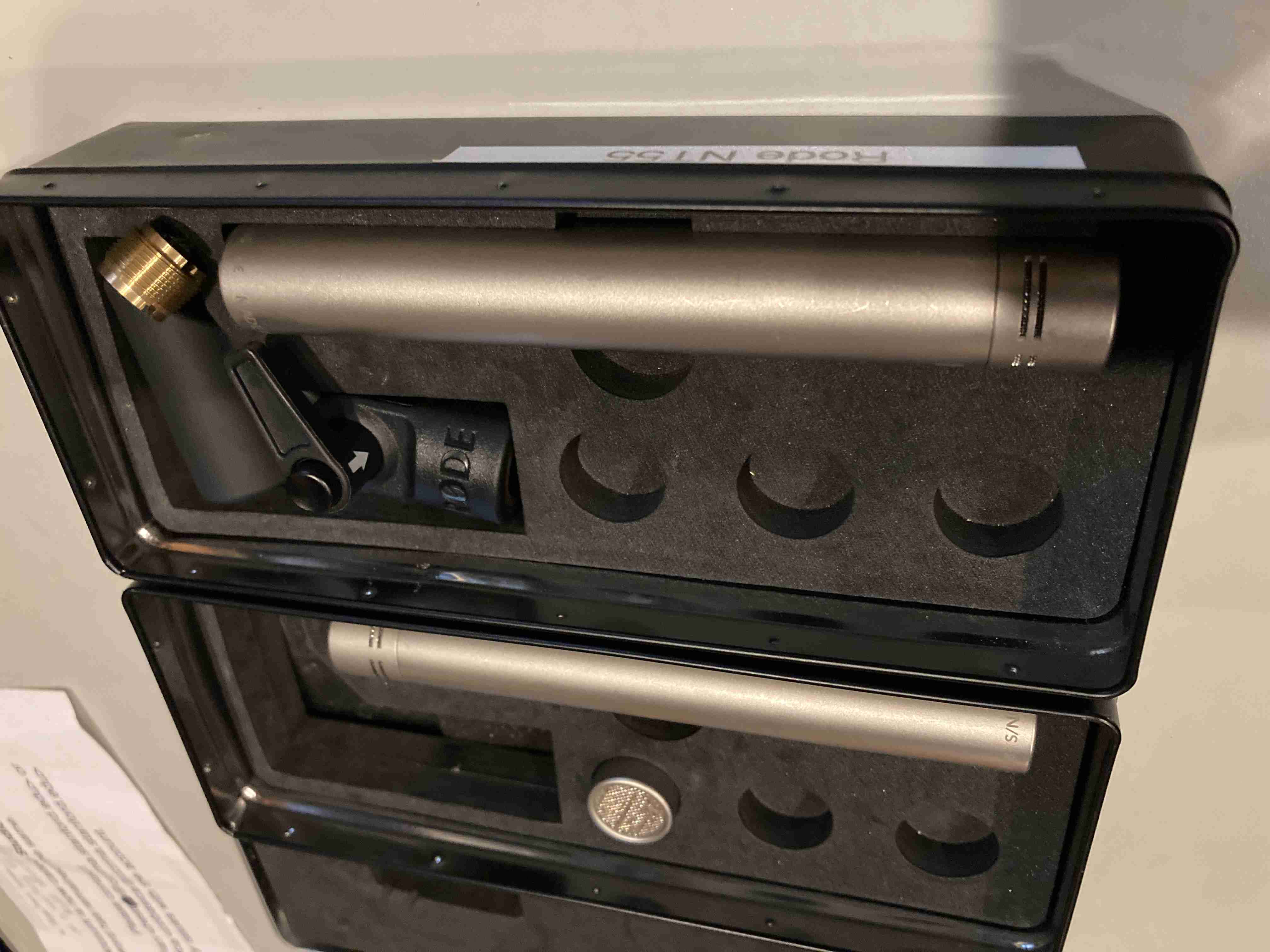
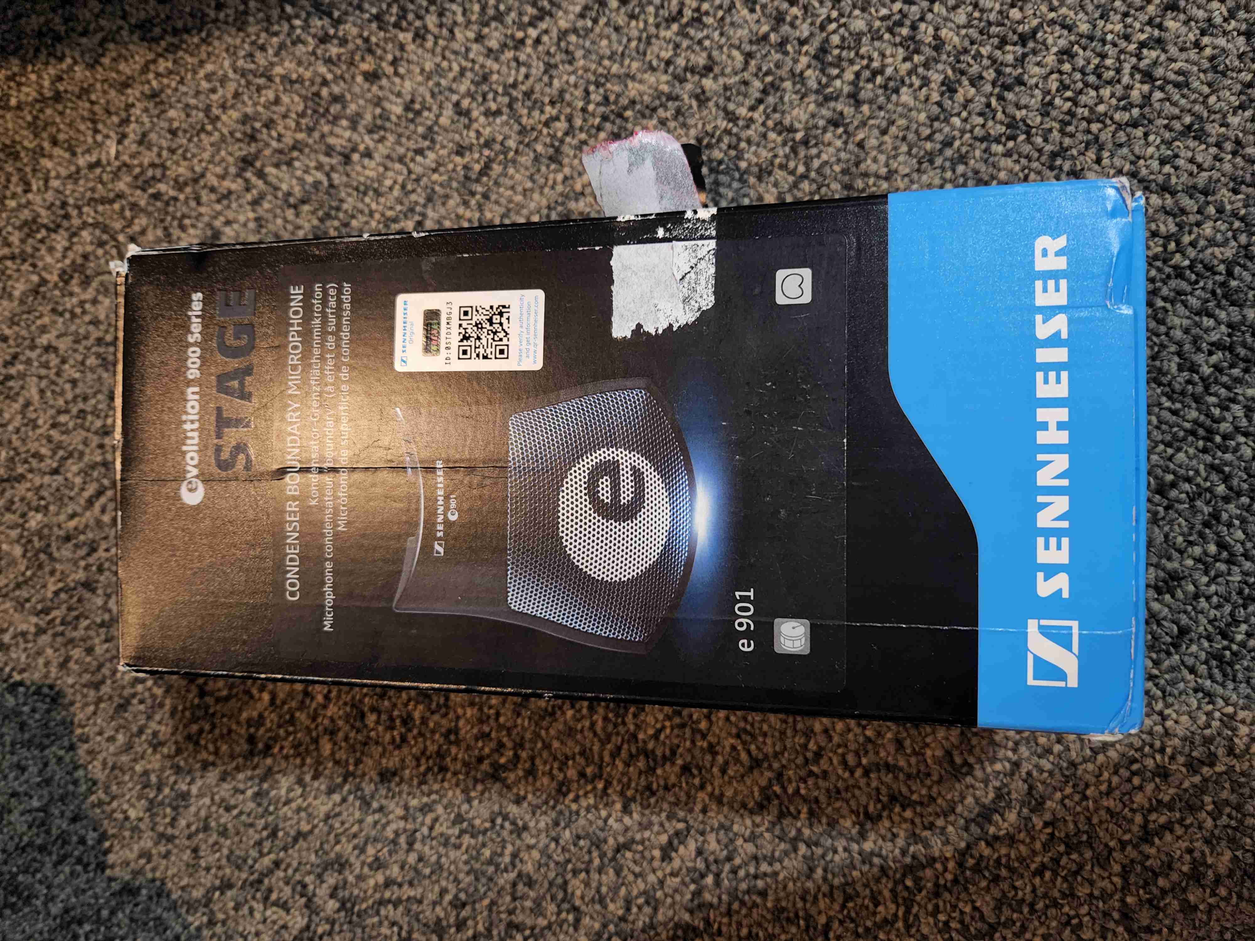
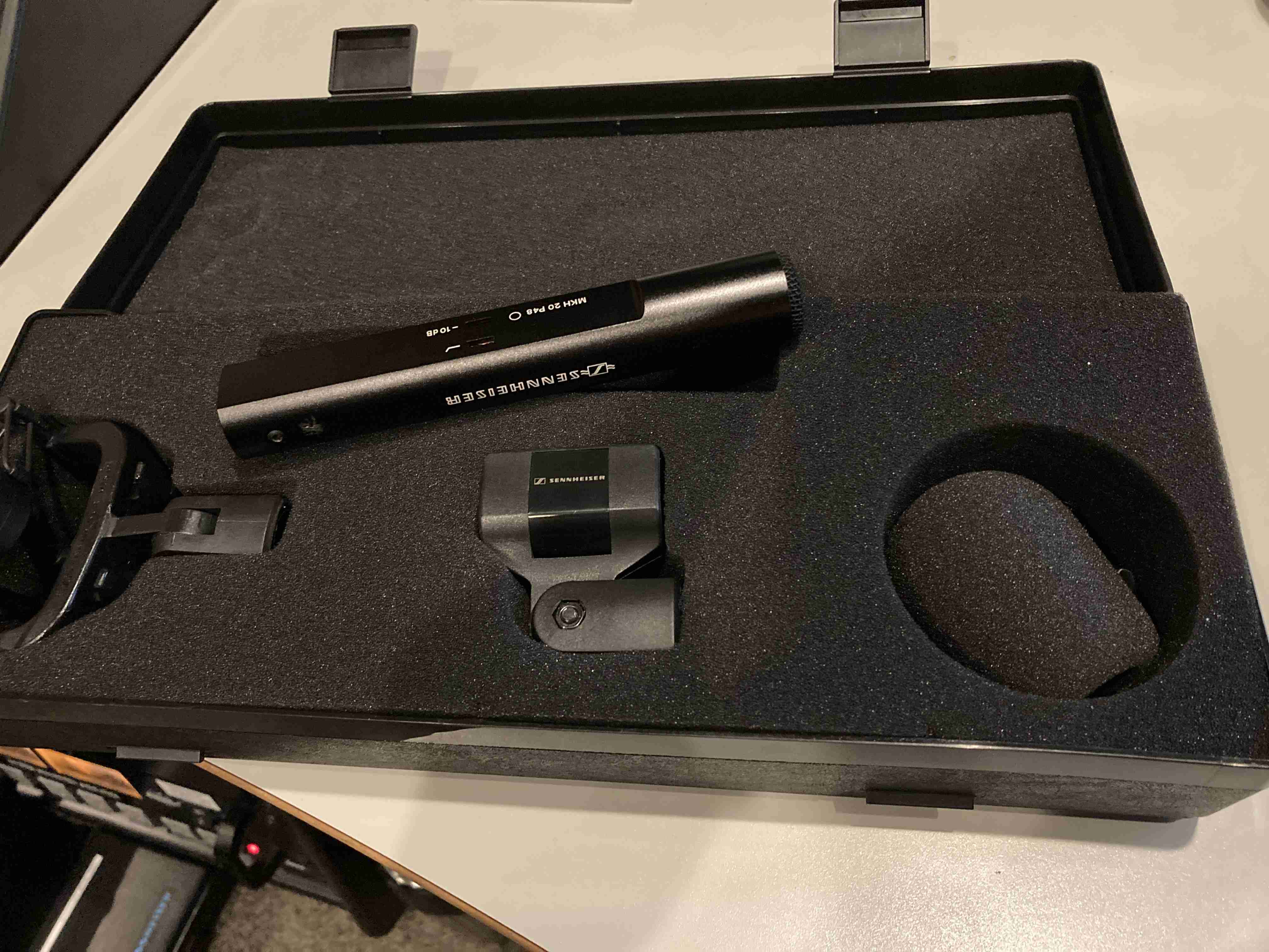
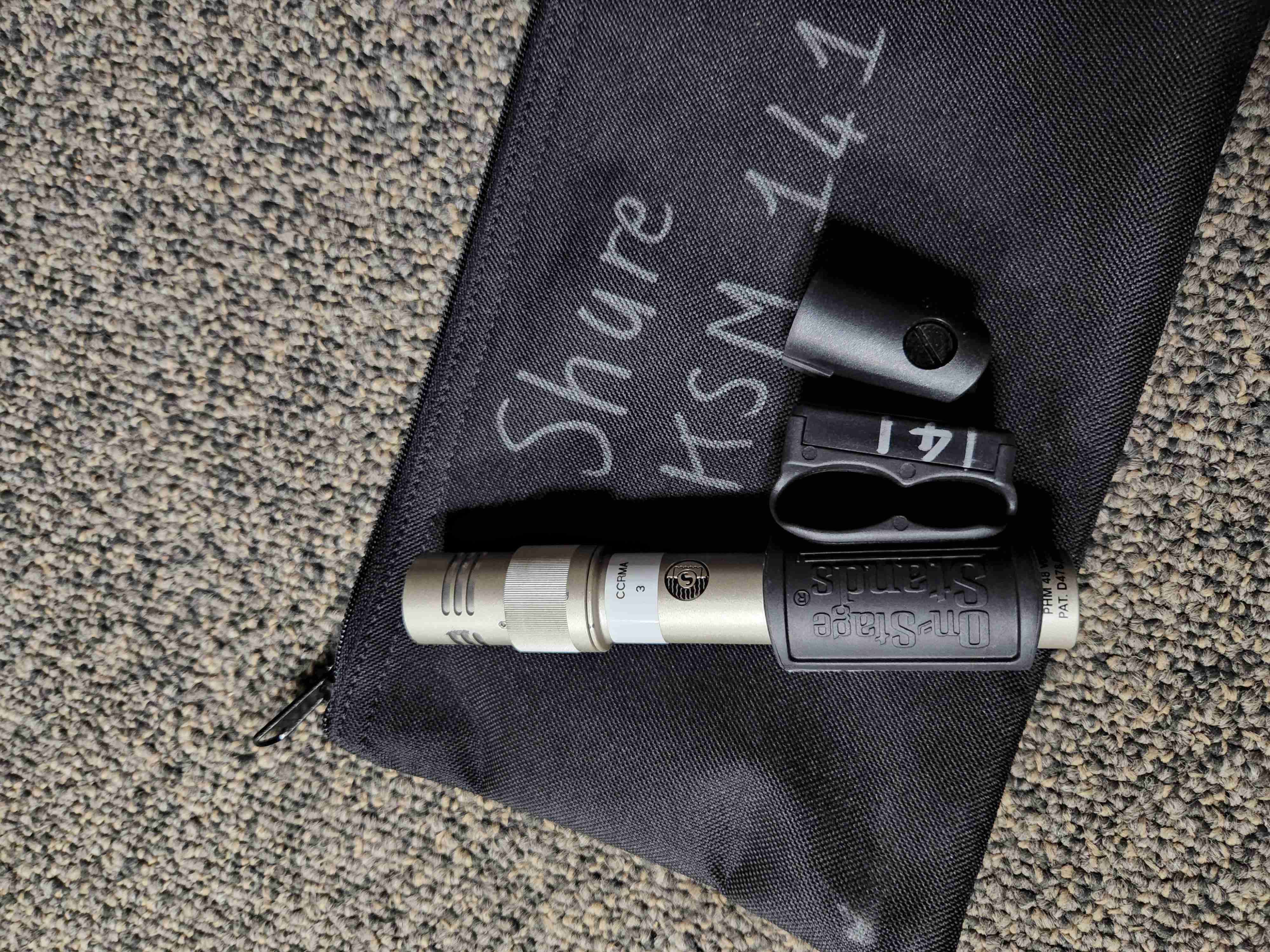
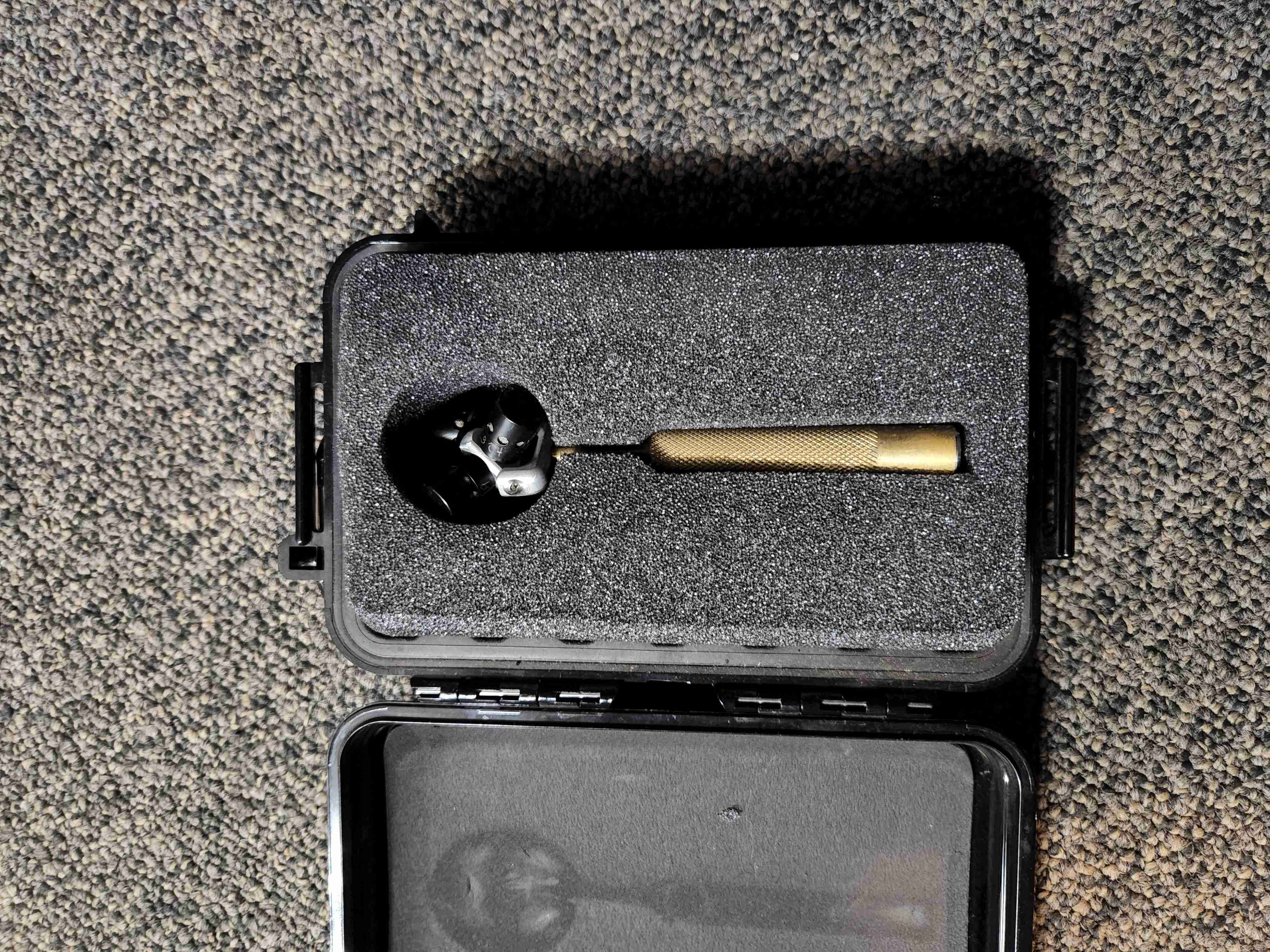
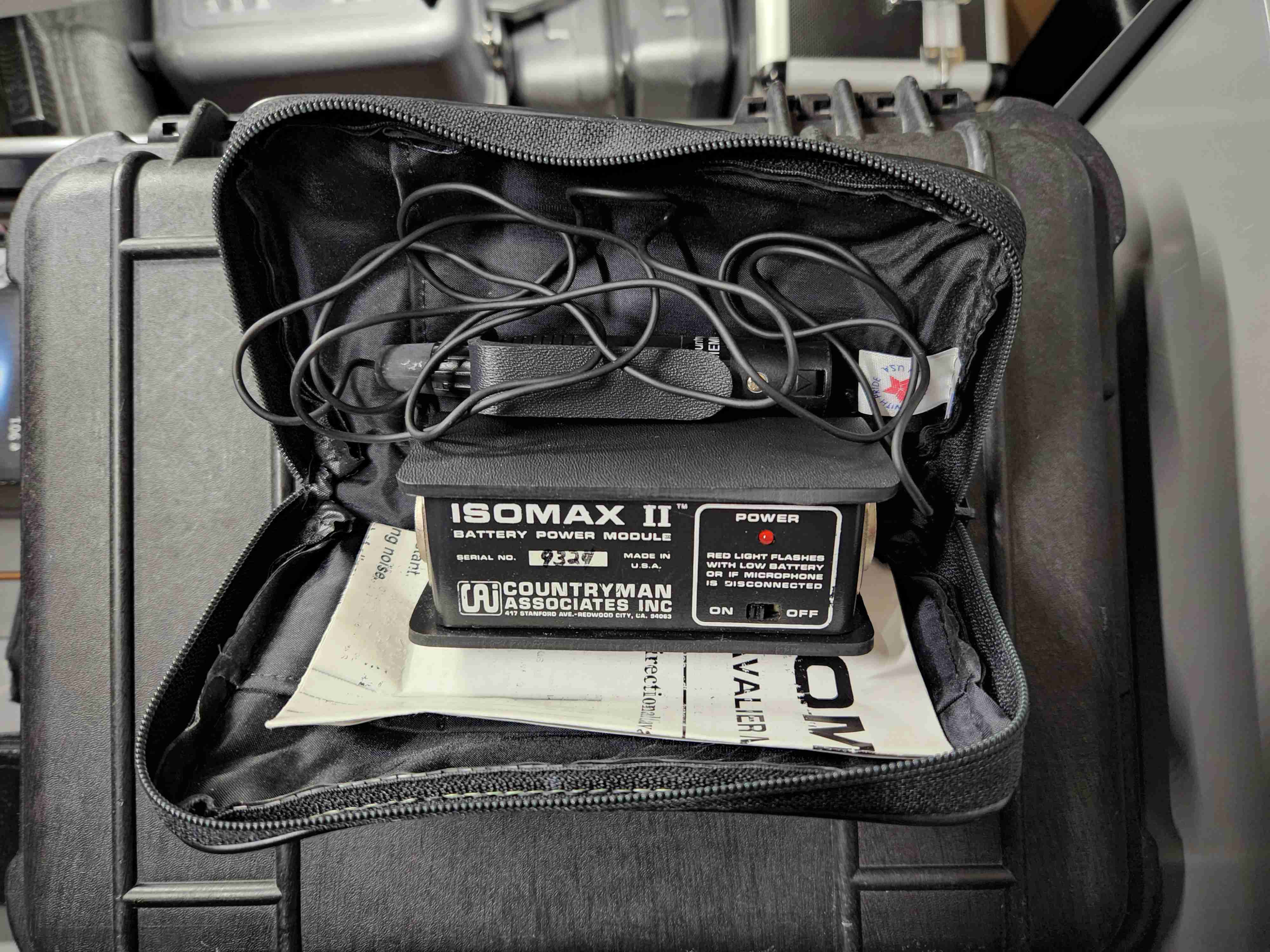
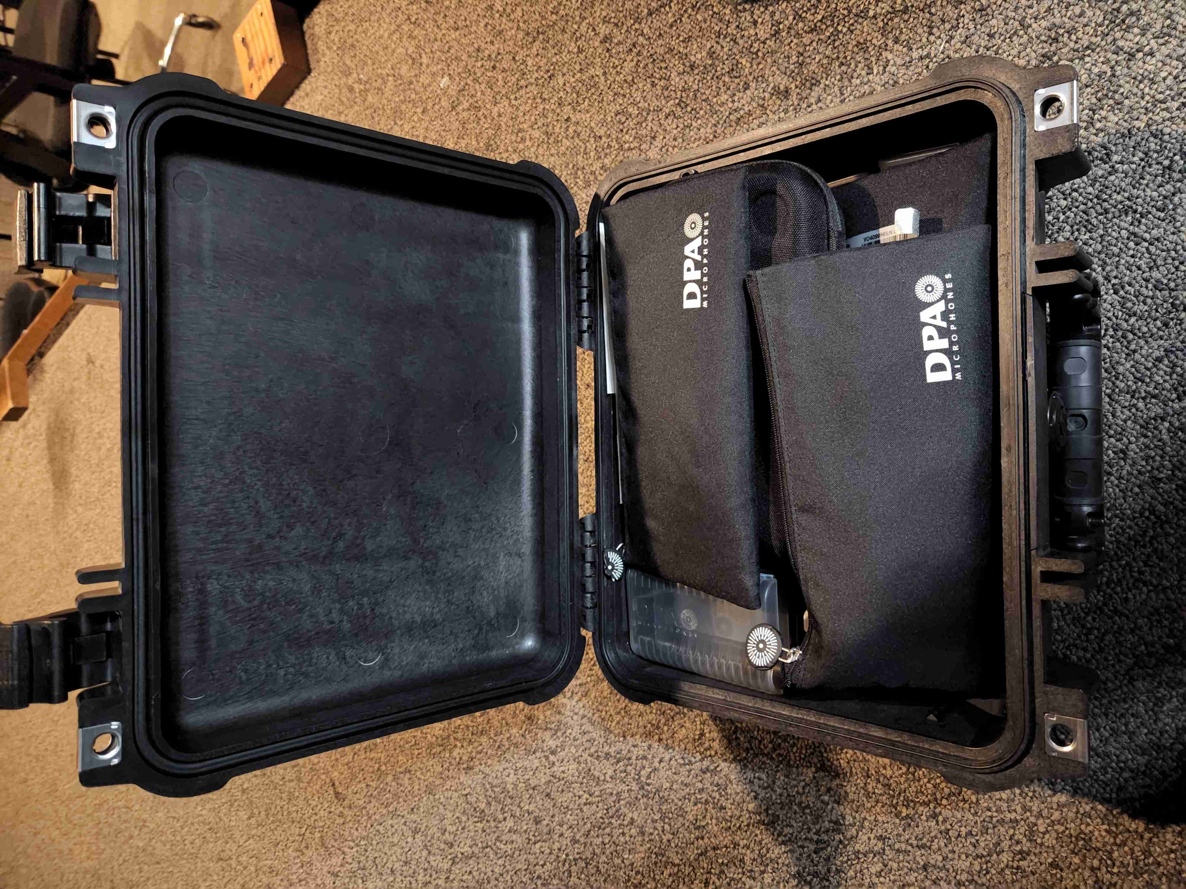
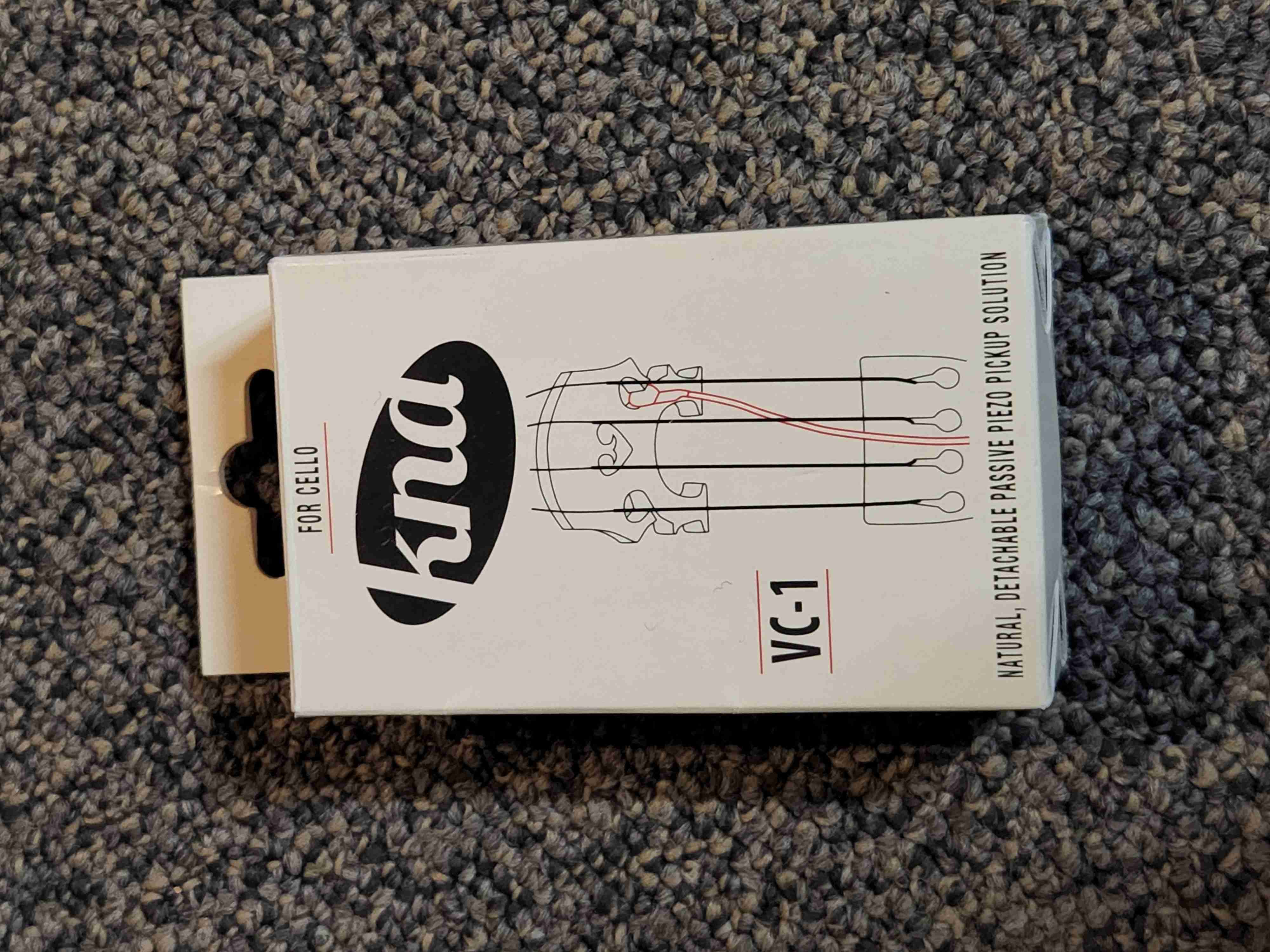
Contains mics and related equipment.
XXX confirm if missing picture
Each room has two crazy button-dials, one for “on” and one for “off”, independently controlling 12 “channels” of lights. When you press the “on” button-dial, the currently-dialed channel turns on, and likewise for the “off” button-dial.
Simple on/off horizontal toggle switch for the “Recording” lights that (by social convention) prevent other people from entering each room.
“CAVIAR” is Eoin Callery’s cute acronym “Center for Augmented/Virtual/Interactive Audio Realities” to describe CCRMA’s in-house system for adding reverb to the live sound in a room via microphones and loudspeakers that magically don’t howl with horrible feedback sounds.
A Mac mini (2018, 3.6 GHz i3, 8GB, macOS “Mojave” 10.14.6) runs the software.
RME
There’s a simpler version of TotalMix that doesn’t let you mix inputs to outputs and it’s just for a DAW.
Total Mix Options / “Operational Mode” offers “Digital Audio Workstaion Mode: straight playback routing, no input mix”
“Hardware inputs” channel strip:
“Hardware outputs” channel strip AN 3/4 and AN 5/6:
Settings to -10dBV
output fader gains to -9 dB
Can save settings to a .tmss file but double-clicking
doesn’t automatically open TotalMix.
The preset file Caviar-totalmix.tmss is in the repo’s
hardware-config subfolder, with all the within-RME gains
and routing. Load it with TotalMix “File” menu
Load Snapshot...
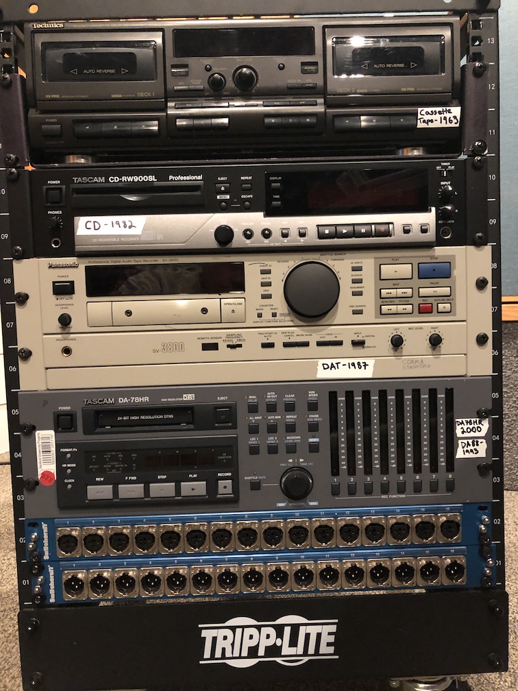
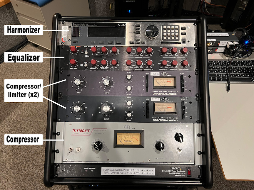
The Legacy Media rack contains (top to bottom):
Note that nothing is wired permanently to the main audio system; we imagine you will connect from these front-facing XLR connectors to the patch bay if you’re crazy enough to want to use any of this.
There was lots of good documentation for the old Recording Studio (which instead centered a Yamaha DM2000 mixer and a Mac Pro (cmn44, “Late 2013” “trashcan” style, 3.7 GHz Quad-Core Xeon E5, MacOS “Sierra” 10.12.6)); this now all needs to be carefully combed through to preserve the still-true bits in new documentation:
This page of CCRMA documentation last committed on Mon Jul 24 21:15:14 2023 -0700 by terry feng. Stanford has a page for Digital Accessibility.
.JPG)