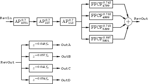
A classical reverberator at CCRMA is JCRev, developed by John Chowning based on the ideas of Schroeder [393]. A block diagram is given in Fig. 2.5, where, in that figure,
An instrument using JCRev simply adds its output, suitably scaled, to the real-time variable RevIn (the global reverberator input sample at the current time). Initially, there are three Schroeder allpass filters in series (Schroeder suggested 5 [386]). These allpass filters may also be referred to as diffusers. The purpose of the allpass filters is to create a dense, colorless, reverberation, exactly along the lines of Schroeder's original paper on the subject [393].
The delay lengths shown in Fig. 2.5 were optimized by ear by John Chowning and others at CCRMA. Schroeder [386] suggests a progression of delays close to
After the allpass filters in Fig. 2.5 is a parallel bank of four feedforward comb filters. Unlike the allpass filters,3.7the comb filters impart coloration to the sound, and they can be considered a simulation of four explicit echoes. The delay lengths in these comb filters may be used to adjust the illusion of ``room size''. This use of feedforward comb filters can be seen as a forerunner of using specific early reflections to foster a desired spatial impression. Note that the four comb-filters could be implemented using a single tapped delay line with 4 taps.
Finally, the reverbator output signal RevOut is fed to the
four audio output channels via four delay lines. The purpose of these
delay lines is to decorrelate the four channels of
reverberation to minimize imaging between speakers, yielding
four simultaneous uncorrelated reverberation outputs instead of only
one. The delay lengths are specified relative to the sampling rate
![]() , and are rounded to the nearest integer.3.8
, and are rounded to the nearest integer.3.8
For stereo listening, Schroeder [386] suggests a mixing matrix at the reverberator output, in place of the final decorrelating delay lines. The goal of the mixing matrix is to produce maximally rich yet uncorrelated output signals [145, p. 111-112].
There is a port of JCRev (with some generalizations and modifications) in the Synthesis Tool Kit (STK) [78]. See files JCRev.cpp and JCRev.h.