Next |
Prev |
Up |
Top
|
Index |
JOS Index |
JOS Pubs |
JOS Home |
Search
Converting a second-order oscillator into a second-order filter
requires merely introducing damping and defining the input and output
signals. In Fig.C.42, damping is provided by the coefficient
 , which we will take to be a constant
When  , the oscillator decays exponentially to zero from any
initial conditions. The two delay elements constitute the
state of the resonator. Let us denote by
, the oscillator decays exponentially to zero from any
initial conditions. The two delay elements constitute the
state of the resonator. Let us denote by  the output of
the delay element on the left in Fig.C.42 and let
the output of
the delay element on the left in Fig.C.42 and let  be the
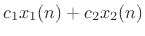
delay-element output on the right. In general, an output signal
be the
delay-element output on the right. In general, an output signal
 may be formed as any linear combination of the state variables:
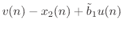
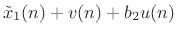
Similarly, input signals  may be summed into the state variables
 scaled by arbitrary gain factors
  .
.
The foregoing modifications to the digital waveguide oscillator result
in the so-called digital waveguide resonator (DWR)
[307]:
 |
 |
 |
(C.148) |
 |
|
![$\displaystyle c[\tilde{x}_1(n) + x_2(n)]$](img4242.png) |
(C.149) |
 |
|
 |
(C.150) |
 |
|
 |
(C.151) |
 |
|
 |
(C.152) |
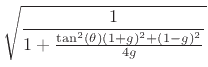
where, as derived in the next section, the coefficients are given by
 |
|
 |
(C.153) |
 |
|
 |
(C.154) |
 |
|
 |
(C.155) |
| |
 |
 |
(C.156) |
where
 denotes one desired pole (the other
being at
denotes one desired pole (the other
being at
 ). Note that
 when
when  (undamped case). The DWR requires only two multiplies per sample. As
seen earlier, when the decay time is set to
(undamped case). The DWR requires only two multiplies per sample. As
seen earlier, when the decay time is set to  (
), one of
the multiplies disappears, leaving only one multiply per sample
for sinusoidal oscillation.
(
), one of
the multiplies disappears, leaving only one multiply per sample
for sinusoidal oscillation.
Figure C.43 shows an overlay of initial impulse responses for
the three resonators discussed above. The decay factor was set to
 , and the output of each multiplication was quantized to 16
bits, as were all coefficients. The three waveforms sound and look
identical. (There are small differences, however, which can be
seen by plotting the differences of pairs of waveforms.)
, and the output of each multiplication was quantized to 16
bits, as were all coefficients. The three waveforms sound and look
identical. (There are small differences, however, which can be
seen by plotting the differences of pairs of waveforms.)
Figure C.43:
Overlay of three resonator impulse
responses, with
![$ \mathbf {B}^T=[1,0]$](img147.png) and
and
![$ \mathbf {C}=[0,1]$](img148.png) , for the (1)
complex-multiply resonator (labeled ``2DR'' for ``2D rotation''), (2)
modified coupled form (MCF), and (3) second-order digital waveguide
resonator (DWR).
, for the (1)
complex-multiply resonator (labeled ``2DR'' for ``2D rotation''), (2)
modified coupled form (MCF), and (3) second-order digital waveguide
resonator (DWR).
![\includegraphics[width=\twidth]{eps/tosc16}](img4258.png) |
Figure C.44 shows the same impulse-response overlay but with
 and only 4 significant bits in the coefficients and signals.
The complex multiply oscillator can be seen to decay toward zero due
to coefficient quantization (
and only 4 significant bits in the coefficients and signals.
The complex multiply oscillator can be seen to decay toward zero due
to coefficient quantization (
 ). The MCF and DWR remain
steady at their initial amplitude. All three suffer some amount of
tuning perturbation.
). The MCF and DWR remain
steady at their initial amplitude. All three suffer some amount of
tuning perturbation.
Figure C.44:
Overlay of three resonator impulse
responses, as in Fig.C.43, but with
and quantization
of coefficients and signals to 4 significant bits.
![\includegraphics[width=\twidth]{eps/tosc4}](img4260.png) |
Next |
Prev |
Up |
Top
|
Index |
JOS Index |
JOS Pubs |
JOS Home |
Search
[How to cite this work] [Order a printed hardcopy] [Comment on this page via email]