The DWN shown in Figure 1.6(b) is unstructured; though the individual acoustic tubes are assumed to have lengths proportional to the delays in the resulting digital waveguides, they do not fall in any regular arrangement. In fact, although we have drawn what appears to be a network spanning two-dimensional space, we have not associated any physical coordinates with the various tube endpoints; it should be clear that losslessness of the digital structure is unaffected by the network topology. At each step in the computer implementation of the DWN, signals are scattered, then shifted--the notion of ``where the signals are'' is unimportant in this abstract setting.
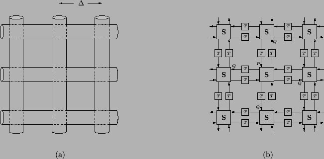
Consider now a regular arrangement, or mesh [198] of acoustic tubes, as in Figure 1.8(a). The tubes are all of length ![]() and admittance
and admittance ![]() , and intersections of four tubes occur at grid points in a Cartesian coordinate system. The resulting DWN is shown in Figure 1.8(b); any scattering junction is linked to its four neighbors to the north, south, east and west by bidirectional delay lines of delay
, and intersections of four tubes occur at grid points in a Cartesian coordinate system. The resulting DWN is shown in Figure 1.8(b); any scattering junction is linked to its four neighbors to the north, south, east and west by bidirectional delay lines of delay
![]() . We have indicated the scattering operation by the letter
. We have indicated the scattering operation by the letter ![]() . Because the admittances of all the tubes are identical, this scattering operation at any junction, from (1.13), has a particularly simple form:
. Because the admittances of all the tubes are identical, this scattering operation at any junction, from (1.13), has a particularly simple form:
 |
Referring to Figure 1.8(b), suppose we initialize this structure with a single incident pressure wave
![]() at location
at location ![]() , the north port of some junction. After scattering, the energy of the incident wave has been distributed among four reflected waves; from (1.16), we will have
, the north port of some junction. After scattering, the energy of the incident wave has been distributed among four reflected waves; from (1.16), we will have
![]() and
and
![]() . After a delay of
. After a delay of ![]() seconds, these reflected waves are then shifted to the inputs of the four neighboring junctions, at points labeled
seconds, these reflected waves are then shifted to the inputs of the four neighboring junctions, at points labeled ![]() . This process is then repeated, and over many time steps, signals will have propagated far from the original excitation at point
. This process is then repeated, and over many time steps, signals will have propagated far from the original excitation at point ![]() . At any time step, however, it should be clear that the sum of the squares of the signals in all the delay registers will be 1.
. At any time step, however, it should be clear that the sum of the squares of the signals in all the delay registers will be 1.
It is possible to view this propagation of signal energy (in a very rough sense) as a discrete time and space version of Huygens' Principle [35], an early description of diffraction phenomena: the advance of a wave-front can be analyzed by considering each point on the wave-front to be the generator of a secondary source of waves. A mesh of acoustic tubes, however, is far from a physical medium supporting multidimensional wave propagation, and a basic question which then arises is: is this network of one-dimensional acoustic tubes approximating the behavior of a two-dimensional acoustic medium?