Next: Type III: Mixed Mesh
Up: The Waveguide Mesh
Previous: Type I: Voltage-centered Mesh
This arrangement is the dual to the previous case. We now set
and
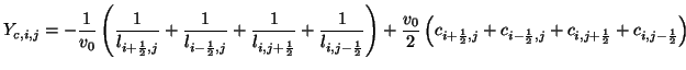
We then have
 |
(4.79) |
for half-integer  and
and  .
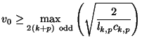
It is rather interesting that in (2+1)D, if we have
.
It is rather interesting that in (2+1)D, if we have  and
and  , this arrangement (and not that of type I) allows the series junctions to be treated as throughs (with sign inversion). We may thus operate at a reduced sample rate in this case. This particular choice of immittances, in the constant-coefficient, lossless and source-free case with
 , yields the original form of the waveguide mesh proposed in [198], and mentioned in §4.2.7. We also note that networks such as this and type I, for which the connecting immittances may vary spatially have also been explored in TLM [29,159].
Next: Type III: Mixed Mesh
Up: The Waveguide Mesh
Previous: Type I: Voltage-centered Mesh
Stefan Bilbao
2002-01-22