Virtual Analog Oscillators
Introduction
Classic waveforms generated by oscillators in analog synthesizers, for example, sawtooth, square and triangular ones, have highly widespread harmonic spectra. While they creates bright and rich sounds, they can cause unpleasant noise when they are trivially implemented in discrete-time domain because harmonic contents above the Nyquist limit are aliased. Here is an example of the aliasing noise produced by a trivial sawtooth oscillator. The fundamental frequency linearly sweeps from 110 to 5000Hz.
| Trivial Sawtooth |
( PLEASE TURN DOWN YOUR VOLUME BEFORE PLAYING! )
As you can hear from the example, frequencies of the aliasing noise goes back and forth as the fundamental increases. In order to remove or suppress it, a number of algorithms have been proposed. We introduce several of them to handle the problem.
Polynomial Bandlimited Impulse Train (PolyBLIT)
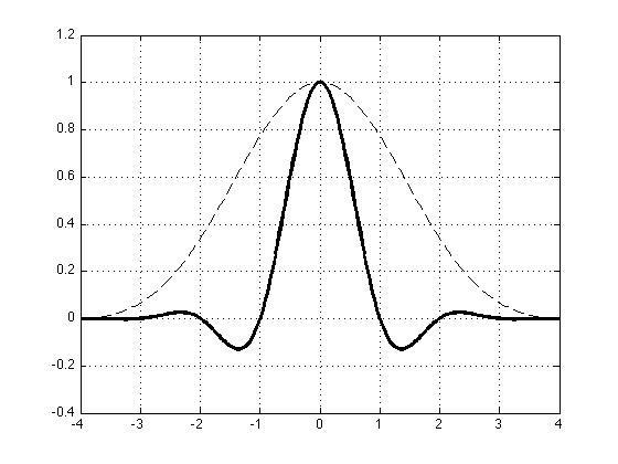
Band-Limited Impulse Train (BLIT) is a basic building block to create various types of bandlimited waveforms. For example, a bandlmited sawtooth oscillator can be derived by integrating a bandlimited impulse train using a one-pole lowpass filter. In fact, a single band-limited impulse corresponds to an impulse response of a lowpass filter. As a result, BLIT-based algorithms end up with designing a lowpass filter. A well-known method uses an ideal brickwall lowpass filter or a sinc function as shown in the top-left of figure 1. Although the sinc function itself is not realizable due to the infinite length, a periodic series of the sinc functions has a closed-form expression, so-called Discrete Summation Formulae (DSF):

where D is period in sample and M is the number of harmonics. This method generates alias-free waveforms, but it is not the best optimized algorithm in terms of efficiency because accurate computation of two sine functions and division are not numerically inexpensive. In addition, when parameters (e.g. M) change over time, it may cause discontinuity (note that DSF assumes that the waveform is stationary).
An alternative method is "sum of windowed sincs (BLIT-SWS)". This is implemented by reading a lookup table which contains an windowed sinc function or more generally coefficients of a customized lowpass filter as shown in the top-right of figure 1. This method can suppress aliasing sufficiently so that it is not perceptually disturbing. However, a large lookup table and linear interpolation is required for high quality.


Figure.1 [Top-Left] sinc function (only the center part shown),
[Top-Right] windowed sinc function
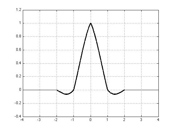
[Bottom-Left] third-order Lagrange Interpolator,
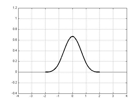
[Bottom-right] third-order B-spline Interpolator
Another method, which is the main topic of my research, is to use fractional delay filters. Conceptually, the idea is to generate every impulse by counting an integer and then passing an impulse to a fractional delay filter such that the sum of the integer delay and the fractional delay is equal to the period in sample. For example, if the period is 169.6154 samples (around 260 Hz at 44.1kHz), then impulses will be genereated at 0, 169.6154, 339.2308 (=169.6154*2), 508.8462 (=169.6154*3) ... Thus, after the first impulse is generated at time 0, the second impulse is generated by counting 169 samples and then feeding an impulse into an fractional delay filter with 0.6154 sample delay. Similarly, the third impulse is genertated by counting 170 (=339-169) and feeding an impulse into the fractional delay filter with 0.2308 sample delay.
There are several types of fractional delay filters. We evaluated Lagrange or B-spline polynomial interpolators, or Thiran allpass filters. Since the two polynomial interpolators are defined in continuous time, delaying an impulse by a fractional sample time is equivalent to sampling discrete points on the continuous-time impulse responses (shown in the bottom of Figure 1) after shifting it by the fractional sample time. Thus, aliasing by the fractional filters is determined by the magnitude responses of the interpolators. Note that the Lagrange interpolator resembles a truncated sinc function with discontinuities between polynomial segments whereas the B-spline is a continuous bell-like curve similar to the Gaussian function. The primary advantage of the fractional delay filters over the BLIT-SWS method is that only simple arithmetic is used for computation without reading a lookup table. Also, the polynomial interpolators span much shorter time than a typical windowed sinc in the BLIT-SWS.
Here are sound examples of sawtooth waveforms generated by the fractional delay filters. The frequency linearly sweeps from 110 to 5000Hz as in the trivial sawtooth waveform above.
| Thiran Allpass filters | Lagrange interpolator | B-spline interpolator | |
| First Order | |||
| Second Order | |||
| Third Order |
(AGAIN, PLEASE TURN DOWN YOUR VOLUME BEFORE PLAYING!)
Note that the first-order B-spline interpolator is the same as the first-order Lagrange interpolator. The aliasing decreases as the order of filters increases. Among them, the third-order B-spline produces minimum aliasing distortion. Analytic analysis and graphical illustrations of spectra and aliasing for the fractional delay filters are described in the paper below. By the way, since Lagrange and B-spline interpolators are expressed as polynomials, the BLITs based on the interpolators could be called "polyBLIT".
More algorithms
We developed more algorithms that efficiently generate bandlimited oscillators. They include BLIT using a feedback delay loop, polynomial-based Bandlimited Step (PolyBLEP), differential polynomial waveform (DPW) and optimized wavetables. Please check out the papers below for details.
Code
- Max/MSP external objects: sawtooth/square oscillators using polyBLIT
- SuperCollider external objects: various oscillators using polyBLIT and DPW (implemented by Nick Collins in University of Sussex, UK)
Publications
- Jussi Pekonen, Juhan Nam, Vesa Välimäki and Julius O. Smith " Optimized Polynomial Spline Basis Function Design for Quasi-Bandlimited Classical Waveform Synthesis ,” IEEE Signal Processing Letters, 2012
- Vesa Välimäki, Jussi Pekonen, Juhan Nam, " Perceptually Informed Synthesis of Bandlimited Classical Waveforms Using Integrated Polynomial Interpolation,” Journal of the Acoustical Society of America, 2012
- Juhan Nam , Vesa Välimäki, Jonathan S. Abel, and Julius O. Smith, " Efficient antialiasing oscillator algorithms using low-order fractional delay filters," IEEE Transactions on Audio, Speech and Language Processing, 2010
- Vesa Välimäki, Juhan Nam, Jonathan O. Smith, and Jonathan S. Abel, " Alias-suppressed oscillators based on differentiated polynomial waveforms," IEEE Transactions on Audio, Speech and Language Processing, 2010
- Jussi Pekonen, Juhan Nam , Julius O. Smith, Jonathan S. Abel and V. Välimäki, " On Minimizing the Look-Up Table Size in Quasibandlimited Classical Waveform Oscillators,” Proceedings of the 13th Int. Conference on Digital Audio Effects (DAFx), September 2010.
- Juhan Nam, Vesa Välimäki, Jonathan S. Abel, Julius O. Smith, "Alias-free virtual analog oscillators using a feedback delay loop," the 12th Int. Conference on Digital Audio Effects (DAFx) , September 2009.