![$\displaystyle \left[\begin{array}{l} p_1^- \\ p_2^- \end{array}\right]$](img448.png) |
![$\displaystyle \left[
\displaystyle
\begin{array}{ll}
\frac{2 \Gamma_{1}}{\Gamma...
...\end{array} \right]
\left[\begin{array}{rr} p_1^+ \\ p_2^+ \end{array} \right]$](img449.png) |
||
![$\displaystyle {\mbox{\boldmath$A$}}\left[
\begin{array}{rr} p_1^+ \\ p_2^+ \end{array} \right]$](img450.png) |
(82) |
Further variations arise from analyzing the two-variable scattering
junction algebraically. In the case of two arbitrary real, positive,
scalar, waveguide impedances, the scattering relations are
The matrix
![]() is a (negated) Householder reflection, and it reflects any
input across the line defined by the eigenvector
is a (negated) Householder reflection, and it reflects any
input across the line defined by the eigenvector
![]() . The quantities involved in
(82) can be set to be
. The quantities involved in
(82) can be set to be
![]() and
and
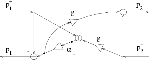
![]() . The signal-flow graph obtained from (84)
is the well-known normalized ladder section. The application
of (82) in the two-port case leads to the signal-flow
graph of Fig. 9.
. The signal-flow graph obtained from (84)
is the well-known normalized ladder section. The application
of (82) in the two-port case leads to the signal-flow
graph of Fig. 9.
It is worth noting that the realization of Fig. 9 can be
implemented, for
![]() , with all coefficients in
, with all coefficients in
![]() , thereby needing only a one-bit integer part. Parametrizing in
terms of the reflection coefficient
, thereby needing only a one-bit integer part. Parametrizing in
terms of the reflection coefficient
![]() can be used to
confine all parameters to the range
can be used to
confine all parameters to the range ![]() , requiring no integer
part. Note also that the junction computation consists of three sequential
multiply-adds, as naturally fits the architecture of many current DSP
chips.
, requiring no integer
part. Note also that the junction computation consists of three sequential
multiply-adds, as naturally fits the architecture of many current DSP
chips.
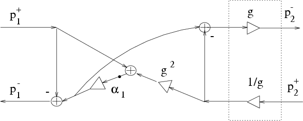
The normalized 2-port junction can also be obtained by applying transformer coupling to a 2-multiply, 3-add unnormalized junction.
Consider the unnormalized ![]() section in Kelly-Lochbaum
form. Defining
section in Kelly-Lochbaum
form. Defining
![]() , we can
write the outgoing pressure wave on the left port as
, we can
write the outgoing pressure wave on the left port as
 |
|||
 |
|||
 |
(84) | ||
 |
|||
 |
(85) |
So far, we have obtained three alternative realizations of the three-multiply, three-add, normalized junction. By comparing Figures 7, 8 and 9, we can say that, for an implementation on a general purpose DSP chip with a parallel multiply-add instruction, the junction of Fig. 9 seems to offer some benefit over the other two. In fact, we can organize the computations into three multiply-adds in series, thus achieving a better pipeline. For VLSI design, the direct implementation of the matrix product using the matrix (84) may be best, since it can be done with four parallel multiplications or CORDIC sections [38].
![\begin{displaymath}
{\tilde {\mbox{\boldmath$A$}}}=\left[
\begin{array}{rr}
\cos...
...ta}) \\
\sin({\theta}) & -\cos({\theta})
\end{array} \right]
\end{displaymath}](img451.png)