Next |
Prev |
Up |
Top
|
Index |
JOS Index |
JOS Pubs |
JOS Home |
Search
An inductor can be made physically using a coil of wire, and it
stores magnetic flux when a current flows through it. Figure E.2
shows a circuit in which a resistor  is in series with the parallel
combination of a capacitor
is in series with the parallel
combination of a capacitor  and inductor
  .
.
The defining equation of an inductor
is
 |
(E.3) |
where  denotes the inductor's stored magnetic flux at time
 ,
is the inductance in Henrys (H), and
,
is the inductance in Henrys (H), and 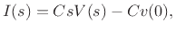 is the
current through the inductor coil in Amperes (A), where
an Ampere is a Coulomb (of electric charge) per second.
Differentiating with respect to time gives
is the
current through the inductor coil in Amperes (A), where
an Ampere is a Coulomb (of electric charge) per second.
Differentiating with respect to time gives
 |
(E.4) |
where
 is the voltage across the inductor in
volts. Again, the current
is taken to be positive when flowing
from plus to minus through the inductor.
is the voltage across the inductor in
volts. Again, the current
is taken to be positive when flowing
from plus to minus through the inductor.
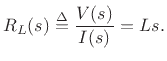
Taking the Laplace transform of both sides gives
by the differentiation theorem for Laplace transforms.
Assuming a zero initial current in the inductor at time 0
, we have
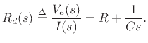
Thus, the driving-point impedance of the inductor is  .
Like the capacitor, it can be analyzed in steady state (initial
conditions neglected) as a simple resistor with value
Ohms.
.
Like the capacitor, it can be analyzed in steady state (initial
conditions neglected) as a simple resistor with value
Ohms.
Subsections
Next |
Prev |
Up |
Top
|
Index |
JOS Index |
JOS Pubs |
JOS Home |
Search
[How to cite this work] [Order a printed hardcopy] [Comment on this page via email]