Synthesis

This page contains a brief overview of each impulse response synthesis method used. These include:

Finite
Element
Image 
Method
RAY
Tracing
Scattering
Delay Network

Image Method

The image method, developed by Jeffrey Borish at CCRMA in the 1980s, approximates the room impulse response between a source and listener by generating a set of virtual sources or “images“ representing the effect of reflecting surfaces on the actual source. The approximation is valid when the wavelength of sound considered is significantly less than the dimensions of the reflecting surfaces modeled. It is used to compute early reflections from large, flat surfaces in a space.

The method may be described by considering that the sound field created by a single source in the presence of an infinite reflecting surface is equivalent to that created by two sources, the original source and an “image“ source positioned and oriented by reflecting the original source hrough the surface. In an enclosed space, the set of virtual sources is formed by first reflecting the source through each of the reflecting surfaces comprising the space. In turn, each of these first-order source images is reflected through each of the reflecting surfaces that has its interior facing the generating virtual source to generate second-order source images. This process is repeated to generate a cloud of image sources that is sufficiently large to produce the desired room impulse response duration.

The room impulse response is then found by summing the responses of the source and virtual sources individually. This is done by first verifying whether each of the image sources is visible to the listener, and then delaying and scaling an impulse emitted by each visible image source according to its distance to the listener, applying any source radiation and listener antenna patterns, and filtering the processed pulse according to the materials properties of the reflecting services encountered between the virtual source and listener.

The racquetball court is a case for which the image method is expected to produce a good approximation to the measured impulse response. And in fact, the impulse responses generated by the image method closely match the early reflection timing and late field energy profile of the measured impulse responses.

Diagram illustrating the modeling of a reflection in the image method as a seperate virtual source
Sound Examples 

Singing

Anechoic (Dry)

Image Method

Ground Truth

Drums

Anechoic (Dry)

Image Method

Ground Truth

Ray Tracing

Several algorithms are used to ensure optimal computation and achieve higher precision in this measurement method. ODEON is a program used for this room modeling and is primarily suitable for geometric models where high modal overlap occurs. For computing, early reflections, a combination of Ray tracing (which incorporates the Image Source method (ISM)) and the Early Scattering method (ESM) is used. The program then switches to the Ray Radiosity method (RRM) for calculating late reflections. While real measurement operates in the pressure domain, these simulations operate in the energy domain. The transition order defines when the program switches from the early-reflection calculation to the late-reflection part. For early reflections, which have significant importance in locating the sound source, several rays are generated and emitted from the sound source. Their specular reflection and corresponding attenuation based on material absorption are recorded until they reach the transition order. Meanwhile, the Early Scattering Method creates a range of early secondary sources that emit scatter rays from the image sources to account for the scattered sound energy. The late-reflections part uses the Ray Radiosity method (RRM), a modified Ray tracing method that applies a detection sphere around the receiver to capture late reflections.

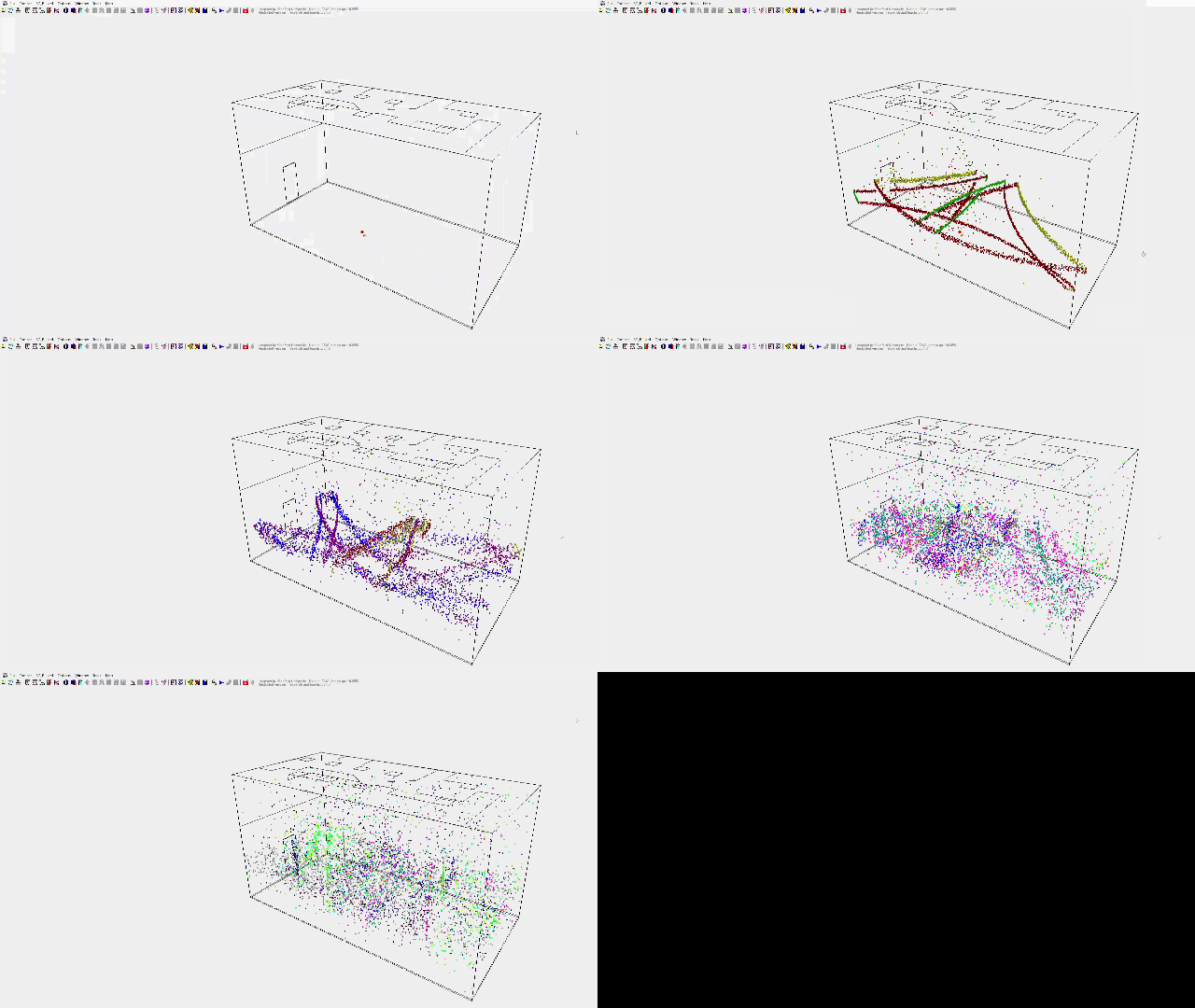
Wave propogation in the horizontal plane to illustrate the impact of scattering and possible flutter echoes.

Sound Examples 

Singing

Anechoic (Dry)

Ray Tracing

Ground Truth

Drums

Anechoic (Dry)

Ray Tracing

Ground Truth

Additional Reading:

  1. Krokstad, A., Strøm, S., Sørsdal, S.: Calculating the acoustical room response by the use of a ray tracing technique. J. Sound Vib. 8, 118–125 (1968)

Scattering Delay Networks (SDN)

Scattering delay networks [1] (SDNs) consist of delay lines connecting wall junctions, that are placed at the location of first-order reflections. The delay line lengths are chosen according to the source-listener positions and room geometry. All the wall junctions are connected to each other via a scattering matrix, which introduces recursion in the network. SDNs can render first-order reflections accurately, and approximate higher-order reflections coarsely. The design is ideal for real-time implementation within dynamic scenes, and generally provides higher perceived naturalness than Feedback Delay Networks since early reflections are modelled correctly. 

In our simulations, we calculated the RIR with the SDN at a sampling frequency of 44.1 kHz. The cuboid room was the same dimensions as the racquetball court. The source was placed at (5.3, 6.7, 1.5) m and the receiver was placed at ( 4.5, 2.7, 1.5) m. The IIR filters calculated from the half-octave band reflection coefficients with warped-Prony’s method are used as wall filters in the SDN to obtain the desired T60. 

Sound Examples 

Singing

Anechoic (Dry)

SDN

Ground Truth

Drums

Anechoic (Dry)

SDN

Ground Truth

Finite Element Method (FEM)

The Finite Element Method [1] is used to obtain the pressure field in the racquetball court. In FEM, a weak formulation is solved by integrating the Helmholtz equation with a weighting function. The integral is the n discretized with shape functions, and solved for specific wave numbers on a fine spatial grid.  The boundary conditions impose the wall absorption filters. Since the FEM is a wave-solver, it gives an exact solution of the pressure field in the court.

In our simulations, we used a sampling frequency of 44.1 kHz. The pressure field is calculated within a cuboid mesh of the same dimensions as the racquetball court. A monopole source is placed at (5.3, 6,7, 1.5) m. To calculate the impedance at the boundary. T60s are estimated from the measurement in half-octave bands. The reflection coefficient is calculated from the measured T60s using Sabine’s equation. A second order IIR filter is fit to the reflection coefficients using warped Prony’s method. From these coefficients, the wall impedance is calculated for a specific wave number. The impedance is imposed as a ‘Robin-type’ boundary condition in the FEM. The weak form is solved with FreeFEM++ [2] with a linear shape function. Unfortunately at this time, no sound examples are available.

Pressure field from 50Hz - 250Hz at every 10Hz

References: 

  1. Mitchell, A. R. "Of the Finite Element Method.” The Mathematics of Finite Elements and Applications: Proceedings of the Brunel University Conference of the Institute of Mathematics and Its Applications Held in April 1972. Academic Press, 2014.   
     
  2. Hecht, Frédéric. "New development in FreeFem++." Journal of numerical mathematics 20.3-4 (2012): 251-266.