Next |
Prev |
Up |
Top
|
REALSIMPLE Top
Dynamic Level Lowpass Filter
In real strings, the spectral centroid typically rises as
plucking/striking becomes more energetic. The EKS dynamic-level
lowpass filter (diagrammed at the far right in Fig.4)
qualitatively models this phenomenon:9
This is another unity-dc-gain one-pole lowpass, with a pole at
 set such that the gain is the same for all fundamental
frequencies [4]. Here we will derive simplified
design formulas.
Assume that the ideal continuous-time filter has the
transfer function
 |
(3) |
where
 denotes the fundamental frequency in
radians per second. This lowpass filter has unity dc gain,
  dB
gain at
  , and rolls off
  dB/octave for
 .10It also happens to be the 1st-order Butterworth lowpass with cut-off
frequency set to
  rad/sec.
To achieve the dynamic level effect, the output of
this filter is linearly panned with its input.
If
  denotes the
lowpass input signal and
  its output, then the formula is
where the level variable ![$L\in[0,1]$](img69.png) may be set to achieve a desired
dynamic level at the Nyquist limit, while
may be set to achieve a desired
dynamic level at the Nyquist limit, while  controls the (lesser)
attenuation at low frequencies as a function of level
  (e.g.,
 ).
At maximum level
  , the lowpass filter is bypassed.
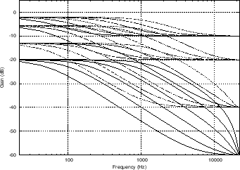
Figure 7 shows a family of filter
responses at four different dynamic levels and six different
fundamental frequencies.
An example GUI specification for the  calculation in Faust is as follows:
L = hslider("dynamic_level", -10, -60, 0, 1) : db2linear;
where db2linear(x) is defined in music.lib as
pow(10, x/20.0).
In [14],11the impulse-invariant and bilinear
transform methods are compared for digitizing the dynamic-level
analog filter Eq. (4), and the bilinear transform method was deemed
preferable because it gives more attenuation of high frequencies,
which helps to reduce aliasing due to later nonlinear processing. A
detailed derivation can be found there. The final digital filter so
designed has the transfer function
 |
(4) |
with
 .
.
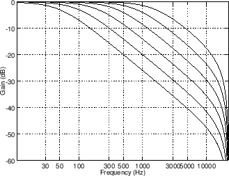
Figure 6 shows a family of magnitude responses for
 for 6 different fundamental frequencies
 .
.
Figure 6:
Dynamic level lowpass filter designed
by the bilinear-transform method with  . The filter
amplitude response is plotted for 6 values of break frequency (50,
100, 200, 400, 800, and 1600 Hz). The sampling rate is
  Hz.
Hz.
 |
Figure 7:
Dynamic level lowpass
filter responses as in Fig.6, but with  ,
,
 ,
,  , and
, and  , corresponding to desired Nyquist-limit
levels of
  ,
,  ,
,  , and
, and  dB, respectively. The dc
level is defined to be one-third the Nyquist-limit level.
 |
Subsections
Next |
Prev |
Up |
Top
|
REALSIMPLE Top
Download faust_strings.pdf
![]() calculation in Faust is as follows:
calculation in Faust is as follows:
![]() (4), and the bilinear transform method was deemed
preferable because it gives more attenuation of high frequencies,
which helps to reduce aliasing due to later nonlinear processing. A
detailed derivation can be found there. The final digital filter so
designed has the transfer function
(4), and the bilinear transform method was deemed
preferable because it gives more attenuation of high frequencies,
which helps to reduce aliasing due to later nonlinear processing. A
detailed derivation can be found there. The final digital filter so
designed has the transfer function
![]() for 6 different fundamental frequencies
for 6 different fundamental frequencies
![]() .
.

