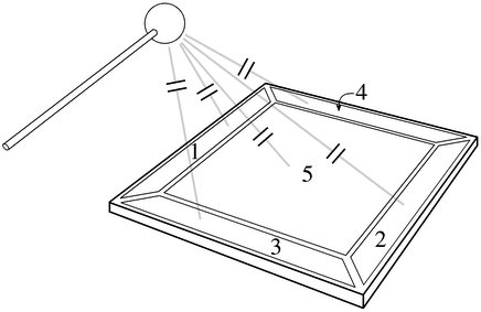
The Radio-Baton is a device which tracks the motions of the tips of 2 batons in a 3 dimensional space. The main components of the system are 2 batons, and a base unit called the ``antenna.'' The tips of each of the batons are shrouded in copper, and 5 copper plates are housed in the base unit. By measuring the electrical capacitance between the tip of the baton and each of the 5 plates, the system is able to localize of the tips of each of the batons. Each of the 5 capacitors will vary as a nonlinear function of the distance between tip of the baton and the copper plate. This is depicted in Figure 46.
Figure 46: The capacitive elements of the Radio Baton
The remainder of the Radio Baton system is shown in Figure 47. Capacitors are devices which exhibit an electrical impedance (the AC counterpart to resistance) which varies inversely proportional to the capacitance of the device. By applying an alternating current of known voltage to the plates of the capacitor, one can determine the impedance, and hence the capacitance by measuring the current flow through the device. This is the basic principle of operation of the radio baton. In the case of the radio baton, the voltage is an AC signal with a frequency of 50kHz. The current through each of the 5 capacitive elements is measured, and converted to a voltage which reflects the magnitude of this current. This voltage is subsequently measured by the ADC converter.
The set of 5 current measurements is processed by an embedded 80186 processor, which is programmed to turn the set or measurements into a position given as a set of 3 cartesian coordinates. An important aspect of this procedure is to compensate for the nonlinear relation between the measured current and that actual position.
Figure 47: Block diagram of the Radio Baton system.