 |
Let's start with a very basic example of the generic problem at hand: understanding the effect of a digital filter on the spectrum of a digital signal. The purpose of this example is to provide motivation for the general theory discussed in later chapters.
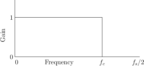
Our example is the simplest possible low-pass filter. A low-pass
filter is one which does not affect low frequencies and rejects high
frequencies. The function giving the gain of a filter at every
frequency is called the amplitude response (or magnitude
frequency response). The amplitude response of the ideal lowpass
filter is shown in Fig.1.1. Its gain is 1 in the
passband, which spans frequencies from 0 Hz to the cut-off
frequency ![]() Hz, and its gain is 0 in the stopband (all
frequencies above
Hz, and its gain is 0 in the stopband (all
frequencies above ![]() ). The output spectrum is obtained by
multiplying the input spectrum by the amplitude response of the
filter. In this way, signal components are eliminated (``stopped'')
at all frequencies above the cut-off frequency, while lower-frequency
components are ``passed'' unchanged to the output.
). The output spectrum is obtained by
multiplying the input spectrum by the amplitude response of the
filter. In this way, signal components are eliminated (``stopped'')
at all frequencies above the cut-off frequency, while lower-frequency
components are ``passed'' unchanged to the output.