A useful technique for junction normalization is by insertion of ideal
transformers. First we define the ideal transformer in the ![]() case (
case (![]() =2) and apply it to the normalization of junctions where
the impedance matrix is diagonal. Then we show a generalization
to the
=2) and apply it to the normalization of junctions where
the impedance matrix is diagonal. Then we show a generalization
to the ![]() case and a non-diagonal impedance matrix.
case and a non-diagonal impedance matrix.
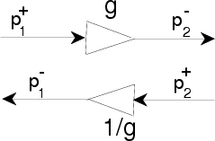
The ideal cascade transformer is a lossless 2-port which scales up pressure by some factor and scales down velocity by the same factor without generating scattering reflections. Signal power is conserved. Since a transformer introduces a discontinuity in both pressure and velocity, it is not physical (although there are physical approximations used in microwave engineering). A conical acoustic tube section can be regarded as an approximate transformer, as can horn loudspeakers.
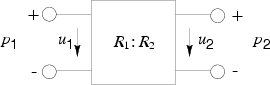
Consider the general two-port diagram in Fig. 11.
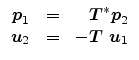
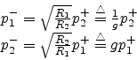
Since a 2-port transformer, by definition, preserves signal power,
we have
| (94) |
 |
(95) |
![\begin{displaymath}
\Sigma=\left[
\begin{array}{ll}0 & {\sqrt \frac{R_1}{R_2}}...
...
\begin{array}{ll}0 & \frac{1}{g}\\ g & 0 \end{array} \right]
\end{displaymath}](img490.png) |
(96) |
The ideal 2-port transformer is depicted in Fig. 11.
In the case of a junction of ![]() waveguides, we can normalize the
junction by making all the waveguide impedances equal. This is accomplished
by inserting
waveguides, we can normalize the
junction by making all the waveguide impedances equal. This is accomplished
by inserting ![]() 2-port transformers, each of them coupling the original
branch impedance at the junction with a unit impedance at each waveguide.
This corresponds to the diagonal
similarity transformation of (32). Of course, we can
choose one of the original branch impedances as reference impedance, so
that inserting
2-port transformers, each of them coupling the original
branch impedance at the junction with a unit impedance at each waveguide.
This corresponds to the diagonal
similarity transformation of (32). Of course, we can
choose one of the original branch impedances as reference impedance, so
that inserting ![]() 2-port transformers will suffice.
2-port transformers will suffice.
The physical interpretation of ideal transformers can be extended more
generally. We define the generalized ideal transformer as a ![]() -port
satisfying the equations [63]
-port
satisfying the equations [63]
It is easy to check that the
definition (98) satisfies the conservation of power:
| (98) |
| (99) |
We can say that the matrix
![]() of (33) acts
as an ideal transformer on the vector of all
of (33) acts
as an ideal transformer on the vector of all ![]() waveguide variables.
waveguide variables.
An important application of the ideal transformer is to decouple scattering junctions from their attached waveguide branches. That is, by modulating the transformer ``turns ratios,'' we may arbitrarily modulate the scattering parameters without also modulating the signal power stored in the waveguide branches.