El Dinosaurio
Dual VCO (Voltage Controller Oscillator) module
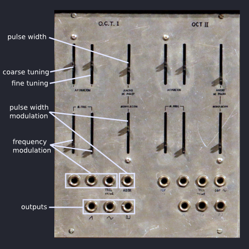
The module includes two identical temperature stabilized voltage controlled oscillators. Each one has sawtooth, triangle and variable width pulse outputs, coarse and fine frequency controls, pulse width control, two frequency modulation inputs with attenuators, a pulse width modulation input with attenuator and two additional frequency control inputs calibrated at 1V/oct (without attenuators).
As is the case with all other modules, some of the jacks in the front panel are "normalled" to suitable sources and simplify the task of patching the modules together.
Circuit Diagram (July 1980)
The main waveform is a triangular wave created through an integrator that is fed opposite polarity currents for each half of the cycle. A comparator creates the pulse waveform and another "flips" and level shifts half of the triangular wave converting it into a sawtooth. A summing amplifier adds all the frequency modulation control voltages and drives one linear to exponential converter transistor for each oscillator.

A CA3046 transistor array IC (5 NPN transistors in a common substrate) is shared by both oscillators and is used to provide the temperature stabilized linear to exponential conversion. Two transistors are used as the exponential converters, another one as a substrate temperature sensor and a third as a heater that maintains the die of the integrated transistor array at a constant temperature. A TL430 constant voltage source is used as a reference (see page 79 of the book Nueva Generación de Instrumentos Musicales Electrónicos, by Juan Bermudez).
The following circuit diagram shows a synchronization circuit that was never incorporated into to the design:

Calibration and Connections
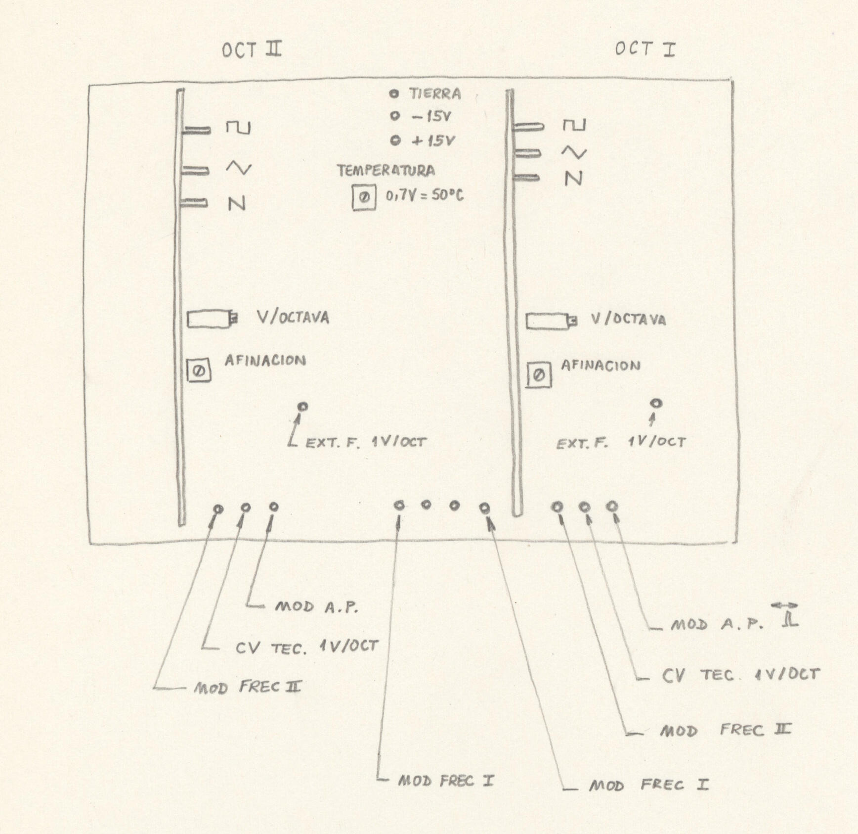
This diagram shows inputs, outputs and the location of the calibration trims of the dual voltage controlled oscillator module.
There are two cermet 10 turn trimpots that calibrate the V/oct setting of each oscillator, and another cermet trimpot that tunes the oscillator (assuming coarse and fine tuning controls in the front panel are at 50%).
An additional trimpot sets the operating temperature of the linear to exponential converter transistors (a base to emisor voltage drop of 0.7 corresponds approximately to 50 degrees centigrade operating temperature - meaning that the synthesizer should stay in tune even in the middle of Summer in Buenos Aires).
Not included in the diagram are two additional trims in each oscillator PCB that control the gain and offset of the circuit that transforms the triangular waveform into a sawtooth.
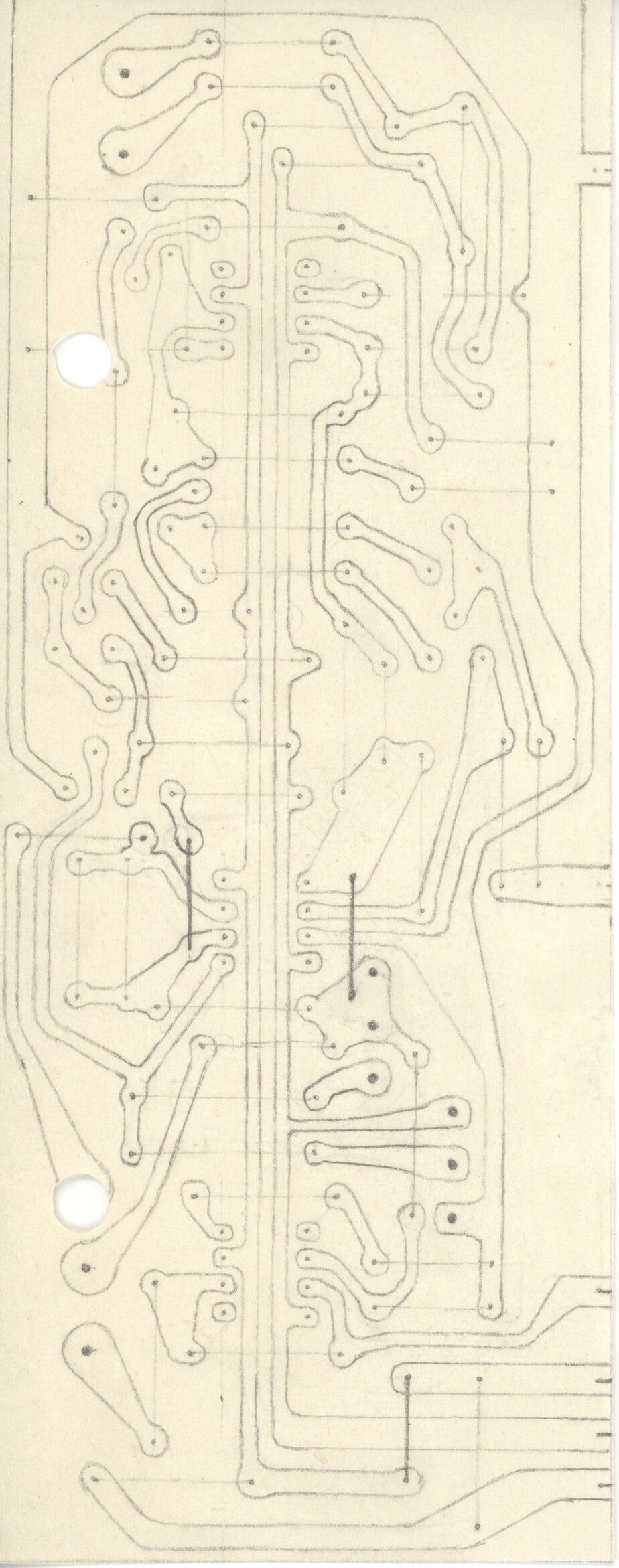
Printed Circuit Boards
Two identical printed circuit boards house the core components of the oscillator and are mounted on a base printed circuit board that houses all front panel linear potentiometers and jacks (there are six pads at the bottom of each oscillator PCB that are soldered to the base board):
This is the base PCB on which the two oscillator boards are mounted. It also houses the voltage control summation amplifier, linear to exponential converter transistor array and the V/oct, tuning and exponential converter temperature calibration trimpots:

Front Panel

This is the front panel template (for one oscillator) that was used to cut the slots for the linear potentiometers and the holes for the 1/4" jacks. Four screws that tap into the linear potentiometers attach the whole assembly to the front panel.
Fernando Lopez-Lezcano

Composer, performer, lecturer and computer systems administrator at CCRMA, Stanford University
Quick Links
El Dinosaurio
Applesauce Modular Mark V
Planet CCRMA
Music & Performances
Of Dinosaurs and Other Creatures
The Well Modulated Dinosaur
The Love Songs of Flying Dinosaurs
El PianoSaurio
Dinosaur He[a]rd!
Wings
Resurrections
Pia[NOT] Etude
The Miraculous Multiplication of Strings
Y Sonó Como Arpa Vieja
Un Esqueleto en la Cocina
The Hidden and Mysterious Machinery of Sound
Modulate me, please?
Space, S[acred|ecular]
Vox Voxel
Toast and Jam
Divertimento de Cocina
Velvet Skin, Heart of Steel
Fugue 1 (Fanfare)
Jurassic Modulations
Earth Songs
Dinosaur Skin
A Very Fractal Cat, Somewhat T[h]rilled
65 Second Bycicle
The Dinosaur At War
Exit Variations
El Dinosaurio Habla
Kitchen <-> Miniature(s)
Instant Knoll
iICEsCcRrEeAaMm
House of Mirrors
With Room to Grow
Knock knock, anybody there?
Three Dreams
Espresso Machine II
Hot'n Cold
Quest
(C)1993-2023 Fernando Lopez-Lezcano. All Rights Reserved.