El Dinosaurio
Dual VCF (Voltage Controller Filter) module

This module includes two voltage controlled filters, the first one (on the left) is a state variable biquad, 12dB/octave multiple output filter. It has simultaneous lowpass, bandpass and highpass outputs. In addition to resonance and filter cutoff frequency controls it has a switch that defines the frequency cutoff range. The second filter (on the right) is a more traditional Moog style low pass filter with a slope of 24dB/octave. The resonance control can lead to oscillation and produces a clean sine wave.
Circuit Diagram
State variable 12dB/oct voltage controlled filter

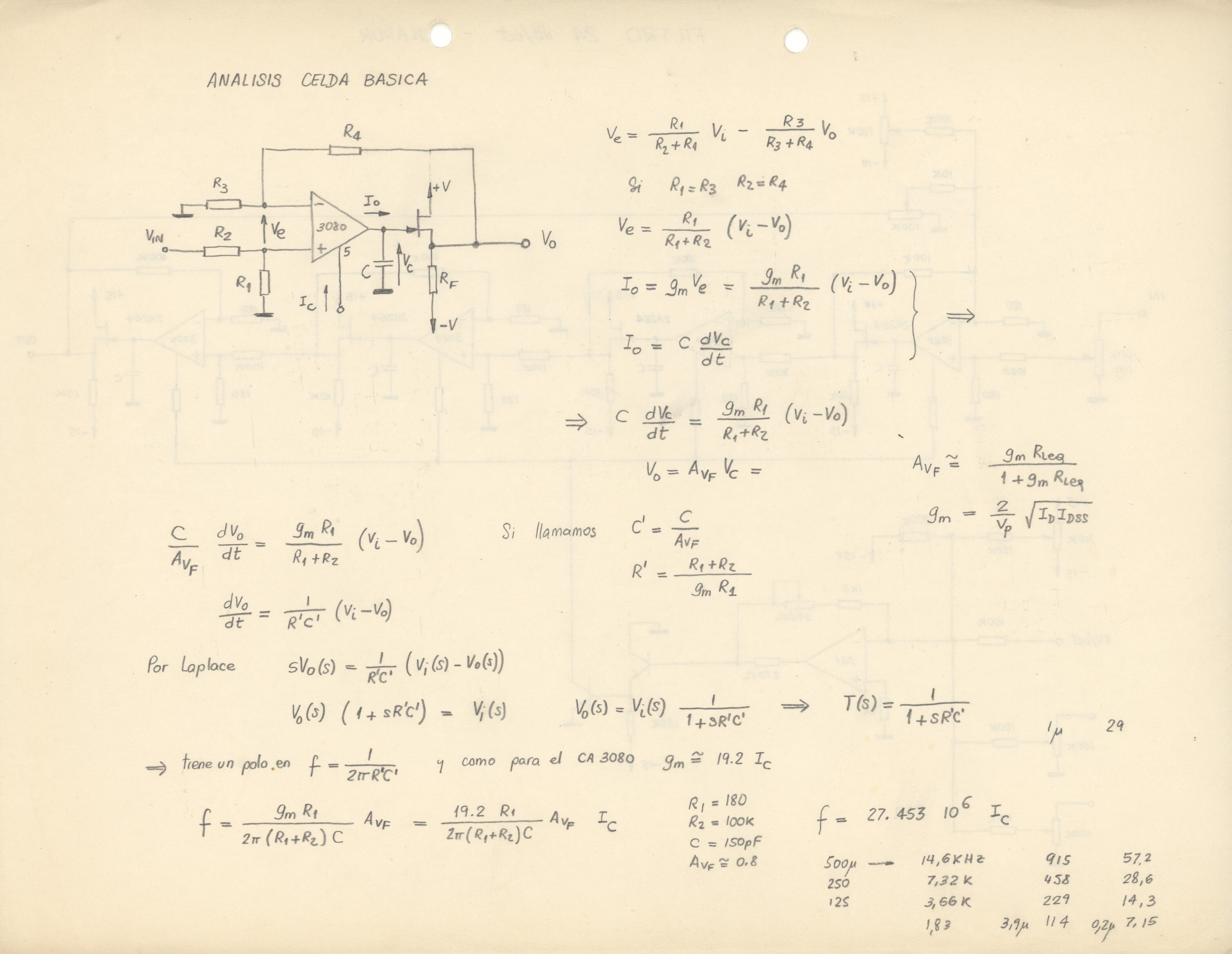
24dB/oct voltage controlled filter

In both filter designs I used transconductance operational amplifiers (CA3080) as current controlled resistors that define the cutoff frequency of the filter cells. While the circuit diagrams do not show it, the linear to exponential converter transistors use the same temperature compensation scheme as in the voltage controlled oscilators (an integrated transistor array is kept as a constant temperature so that the exponential converter transistors do not drift).
This is the basic analysis of an individual filter cell that was used to derive the values of the components:
Additional documentation:
- Basic analysis of the state variable filter
- Final circuit diagram of the state variable filter
- Design of a tentative temperature compensation circuit (November 1979) (more details, plot of temperature compensation)
Calibration and Connections

This diagram shows inputs, outputs and the location of the calibration trims of the dual voltage controlled filter module.
Each filter has a tuning trimpot and a V/oct trim for calibrating voltage to frequency conversion. As is the case with the VCO a trim potentiometer defines the operating temperature of the integrated transistor array. And additional trim not shown in the circuit diagram above minimizes the sinewave distortion when the 24dB/oct filter is driven into oscillation.
Printed Circuit Boards
Two printed circuit boards house the core components of the filters and are mounted on a base printed circuit board that houses all front panel linear potentiometers and jacks.
State variable 12dB/oct filter:

24 dB/oct lowpass filter:

This is the base PCB on which the two filter boards are mounted. It also houses the voltage control summation amplifier, linear to exponential converter transistor array and the V/oct, tuning and exponential converter temperature calibration trimpots:

Fernando Lopez-Lezcano

Composer, performer, lecturer and computer systems administrator at CCRMA, Stanford University
Quick Links
El Dinosaurio
Applesauce Modular Mark V
Planet CCRMA
Music & Performances
Of Dinosaurs and Other Creatures
The Well Modulated Dinosaur
The Love Songs of Flying Dinosaurs
El PianoSaurio
Dinosaur He[a]rd!
Wings
Resurrections
Pia[NOT] Etude
The Miraculous Multiplication of Strings
Y Sonó Como Arpa Vieja
Un Esqueleto en la Cocina
The Hidden and Mysterious Machinery of Sound
Modulate me, please?
Space, S[acred|ecular]
Vox Voxel
Toast and Jam
Divertimento de Cocina
Velvet Skin, Heart of Steel
Fugue 1 (Fanfare)
Jurassic Modulations
Earth Songs
Dinosaur Skin
A Very Fractal Cat, Somewhat T[h]rilled
65 Second Bycicle
The Dinosaur At War
Exit Variations
El Dinosaurio Habla
Kitchen <-> Miniature(s)
Instant Knoll
iICEsCcRrEeAaMm
House of Mirrors
With Room to Grow
Knock knock, anybody there?
Three Dreams
Espresso Machine II
Hot'n Cold
Quest
(C)1993-2023 Fernando Lopez-Lezcano. All Rights Reserved.