MFOS Noise Toaster
Kurt James Werner mod / how-to
Intro
I designed this mod in Autumn 2013, as part of an analog synthesizer group at CCRMA. Several of us (me, Romain Michon, Tim O'Brien, Gina Collechia, and Myles Borins) decided to build Music From Outer Space (MFOS) Noise Toaster kits as a first project in building analog synthesizers. Check out Romain's write-up as well. The Noise Toaster was my first MFOS project, and I can definitely recommend it (with or without my mod!). Check them out at http://www.musicfromouterspace.com.
I had read Ray Wilson's "Make: Analog Synthesizers" book over the summer, so I was familiar with the design of the Noise Toaster. After studying the design some more, I was confident I would be able to modify the normalized switching architecture of the Noise Toaster into a modular / patchable architecture. This opens up the noise toaster to all sorts of cool signal flows that are not available in the original design.
As well as opening up the architecture of the synthesizer and making it patchable / modular, I wanted to design a mod that involves as few alterations to the Noise Toaster PCB as possible, and avoids using extra components that are not part of Ray's kit. To this end, my design involves cutting only a single trace on the PCB, desoldering one end of a single resistor (or, just not attaching it to begin with), and involves no extra parts (except for the banana jacks). Check out a video of the finished product.
This write-up describes the modifications that make a Noise Toaster modular / patchable. This write-up should be used in conjunction with Ray Wilson's very detailed article "MFOS NOISE TOASTER Lo-Fi Noise Box". I'll only describe my modifications, and some discussion of how they work. I'll try to organize it similarly to Ray's article, to make it easy to use them side-by-side.
Bill of Materials
- Music From Outer Space Noise Toaster Kit - you can get these from Ray Wilson's website
- Banana Jacks - I like the Johnson/Emerson banana jacks, which you can get from Digikey. Here is a summary of the banana jacks used, and the part numbers, if you want to order them from DigiKey or anywhere else. Of course, you could use something other than banana jacks, or banana jacks from another manufacturer.
| Color | # | manufacturer part # | DigiKey part # |
|---|---|---|---|
| Black | 9 | 108-0903-001 | J152-ND | Red | 2 | 108-0902-001 | J151-ND | Orange | 1 | 108-0906-001 | J356-ND | Yellow | 1 | 108-0907-001 | J154-ND | Green | 1 | 108-0904-001 | J153-ND | Blue | 3 | 108-0910-001 | J155-ND | White | 1 | 108-0901-001 | J150-ND |
Schematic page 1 (view as PNG)
Overview
These schematics (page 1 & 2) show my modifications to Ray's originals. I'll go through them section by section and describe the mods to each, but most changes are just an application of one simple principle: make things patchable. I'll briefly desribe each part of the circuit (only enough to try to give context to my mods), and how I modified it.
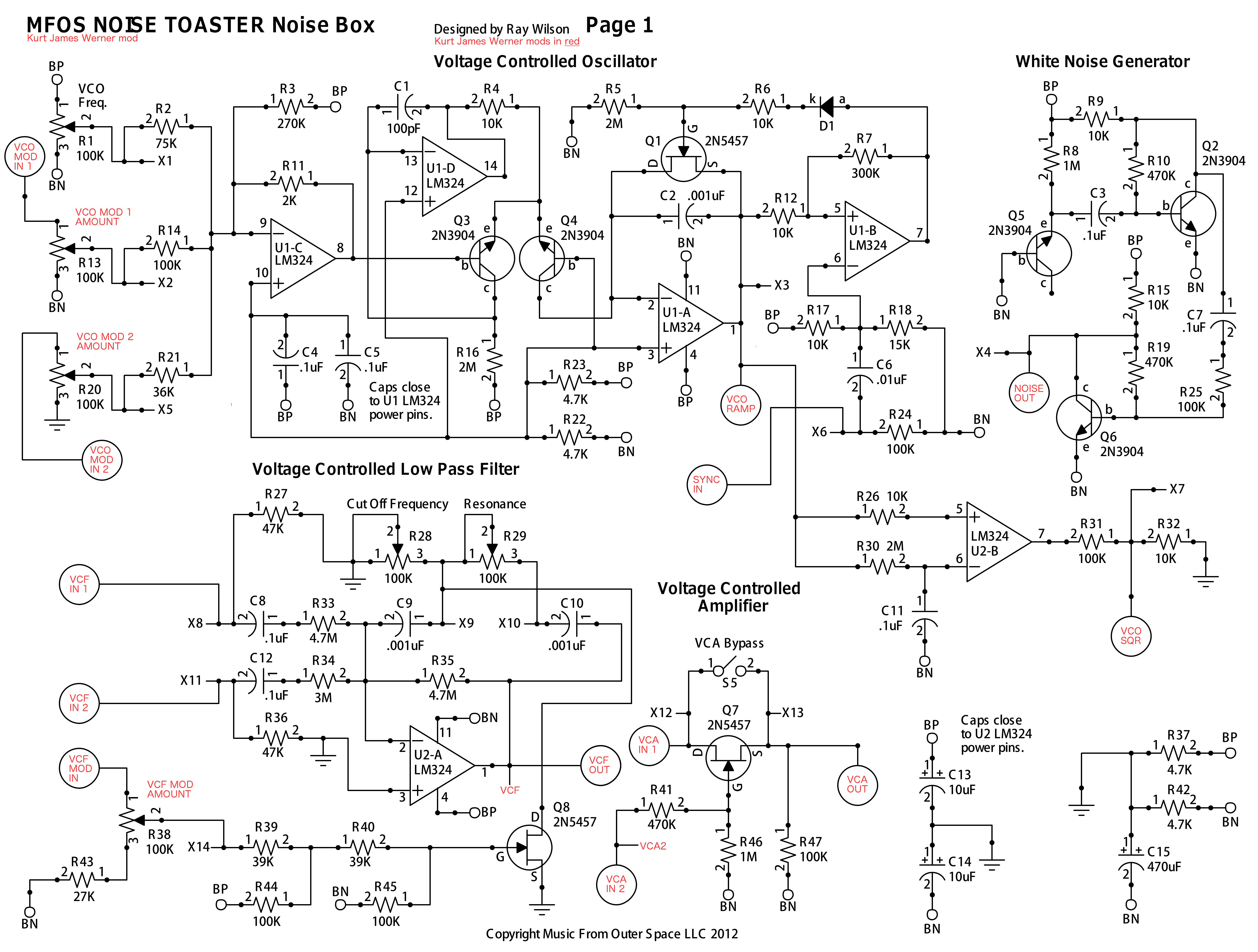
Voltage Controlled Oscillator (VCO)
Pre-modification, the VCO had its frequency set by a knob (R1), and modified by inputs from the LFO and Attack-Release Envelope Generator (AREG). The depth of each modification is controlled by two additional knobs (R13 & R20), and the AREG's effect can be removed entirely with a switch (S1). This works by using op-amp U1-C (an LM324) as an inverting summer, with its output voltage applied to the voltage-controlled ramp-core oscillator. Each knob controls how much of each modulation source contributes to the frequency modulation. See Ray's article for an in-depth explanation.
My mod simply involves removing switch S1 and replacing the hard-wired LFO and AREG inputs with banana jacks (labelled "VCO MOD IN 1" & "VCO MOD IN 2" on my schematics), so anything can be patched in. I like these banana jacks from Johnson/Emerson, they come in a lot of colors. Now, the two knobs control how much each arbitrary modulation source contributes to the frequency modulation. If no modulation source is connected to VCO IN 1, the pot will actually still control how much of a DC bias is applied to the summer (like R3 does to battery positive (BP)). This happens on account of potentiometer R13 having its third lug connected to battery negative (BN). If no modulation source is connected to VCO IN 2, there should just be no effect, since the third lug of potentiometer R20 is connected to ground.
Pre-modification, the VCO takes a sync input (labeled B) from the square output of the LFO. This effect can be turned on or off by switch S2.
My mod simply involves removing S2, and wiring node X2 to a banana jack (labelled "SYNC IN"). Now anything can be patched in as a source of the ramp core's sync. Signals with sharp edges, and whose frequency is not significantly lower than the VCOs frequency still work best. Noise or filtered noise can be great.
Pre-modification, the VCO produces both a ramp output and a square output. These end up presented to the VCF input, and one (or neither) is selected with switch S3.
My mod simply involves wiring these outputs out to banana jacks (labelled "VCO RAMP" and "VCO SQR" on my schematics). Now, the ramp and square waves can be patched anywhere, not just to the input of the VCF!
Let's discuss a few other mods that could be added here (though I haven't tested these). It would be simple to follow the pattern set by the three inputs to add additional modulation inputs to the VCO. Since I wanted my base mod to use only parts included in the kits, I just stuck with two modulation inputs. If you like the behavior (vis a vis range and biasing when disconnect) of the first or second modulation source more, it would be simple to change either by changing what the third lug is connected to (BN or ground). Also, the input resistors (R2, R14, R21) were chosen to compensate for the differences in output voltage range of the LFO, AREG, and the VCO Freq voltage divider. If you want them to all respond identically, you should make R2/14/21 the same value, and connect the third lug of each potentiometer to BN.
Voltage Controlled Filter (VCF)
Pre-modification, the VCF can take up to two audio sources as inputs. The first is chosen from the square wave output of the VCO, the ramp wave output of the VCO, or nothing (selected by switch S3). The second is either the output of the White Noise Source (WNS) or nothing (toggled by switch S4).
My mod involves removing S3 and S4, and wiring nodes X8 and X11 to banana jacks (labelled "VCF IN 1" & "VCF IN 2" on my schematic). Now you can patch anything into the VCF!
Pre-modification, the VCF can accept a cutoff modulation source from either the LFO or the AREG (or nothing), controlled by switch S6. The amount of effect this modulation source has on the cutoff frequency is controlled by potentiometer R38.
My mod involves removing S6, and wiring lug 1 from potentiometer S6 to a banana jack (labelled "VCF MOD IN" on my schematic). Now you can patch anything into the VCF as a cutoff frequency modulation source.
Pre-modification, the output of the VCF (pin 1 on op-amp U2) is wired directly to the input of the Voltage-Controlled Amplifier (VCA), the drain of transistor Q7.
This part of my mod is a little tricky. You have to cut the trace that connects the VCF's output to the VCA's input (at the drain of Q7). Here's where to make the cut on the PCB (red arrow points at it):
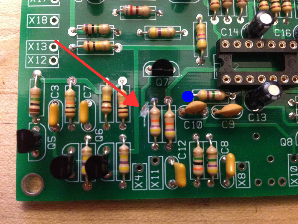 I started making the cut with an exacto knife, but switched to a dremel tool. If you cut down from right above this trace, you don't run much of a risk of cutting other traces on either side of the board (hold the board up to a light if you need convincing). Now, somewhere on the node connecting U2's pin 1, C10, and R35 has to be wired out to a banana jack (labelled "VCF OUT" on my schematic; the node is also labelled "VCF," this is what you should look for on the front panel wiring diagram later). To me, it seemed easiest to do this on the left leg of R35 on the component side (labelled with a blue dot on the above picture).
Let's discuss a few other mods that could be added here (though I haven't tested these). Like in the VCO, the input resistors (R33 & R34) were chosen to compensate for the differences in output voltage ranges of the SQR and RMP outputs of the VCO, and the WNS. If you want the two inputs to respond identically, you should make R33/34 the same value.
Voltage Controlled Amplifier (VCA)
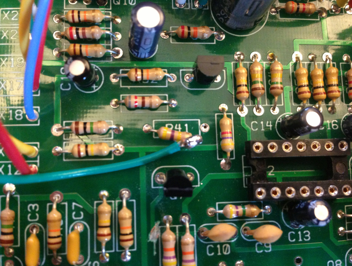
Pre-modification, the VCA takes one input from the output of the VCF, and one input from the AREG. Transistor Q7 is an N-channel JFET used in a voltage-controlled resistor mode, so the voltage applied at the gate (a portion of the AREG's voltage, attenuated by the voltage divider of R41/46) changes the drain-source resistance of Q7. This changes how much the voltage divider formed by Q7 and R47 attenuates the VCF output. Switch S5 lets you short the drain and source of Q7, bypassing the VCA.
If you've already cut the trace between the output of the VCF and the drain of Q7, this part of my mod is simple. The first input of the VCA can simply be wired from node X12 to a banana jack (labelled "VCA IN 1" on my schematic). The end of R41 that is not connected to Q7's drain should be disconnected from the PCB (or, not connected to begin with), and this can be wired to a banana jack (labelled "VCA IN 2" on my schematic; the node is labelled "VCA IN 2," this is what you should look for on the front panel wiring diagram later). See a picture of what this means for the PCB below.
Now, you can patch any two signals into the VCA! As Ray mentions in his article, this VCA is "LO-FI."
Pre-modification, the output of the VCA (the source of Q7, node X13) is wired directly into the 1-Watt Audio Amplifier, through the 1st lug of potentiometer R66.
My mod involves wiring node X13 to a banana jack (labelled "VCA OUT") instead. Now, you can patch the VCA output anywhere!
White Noise Generator
Pre-modification, the output of the WNS can be applied to the input of the VCF with switch S4.
My mod involves simply wiring the output of the WNS (node X4) to a banana jack (labelled "WNS" on my schematic).
Schematic page 2 (view as PNG)

Low Frequency Oscillator
Pre-modification, the LFO's square wave output was hardwired to the VCO's sync switch (S2). The LFO's output was hardwired to one of the VCO's Mod Depth inputs, and could be chosen as a VCF Mod Source. The LFO waveform (square, integrated square, or differentiated square) was selected using switches S7 & S9. The output of op-amp U2 (pin 8) is the square wave output. The differentiated square wave is produced by taking the output of the passive first-order lowpass section formed by R56 and C19 (a first-order lowpass filter will differentiate frequencies that are deep in its stopband). The integrated squarewave is produced by taking the output of the first-order highpass section formed by C17 and whatever resistive path to ground it has (a first-order highpass filter will integrate frequencies that are deep in its stopband)
My mod involves wiring these outputs directly to banana jacks (labelled "LFO SQR," "LFO INT," & "LFO DIFF" on my schematics). The capacitor C17 is mounted between the "LFO SQR" and "LFO INT" banana jacks (remember, switch S7 has been removed).
I think that the integrated square wave might be improved by wiring in a path from the second terminal of C17 to ground or BN. This used to be provided by whichever input the integrated square wave was applied to. But, since each wave can be patched anythere now, its concievable you could patch it to somewhere where it would not form a nice first order highpass filter (e.g. if it were patched to the first input of the VCA). These are the least stiff outputs of any of the Noise Toaster's parts, so actually I feel like it isn't that big of a deal (I still haven't tried this out). It could be nice to replace the resistors in these first-order passive sections with potentiometers, to let you sweep the cutoff frequencies and control the wave shape of the integrated square wave.
Attack Release Envelope Generator (AREG)
Pre-modification, the output of the AREG is taken from node X18, labelled "ARG" on the original schematic. This can be applied to the second Mod Depth input of the VCO using switch S1, or can be applied as the VCF Mod Source with switch S6.
My mod inolves simply wiring this output to a banana jack (labelled "ENV OUT" on my schematics).
One Watt Audio Amplifier
Pre-modification, the amp always took its input from the VCA's output.
My mod involves simply wiring this input (the 1st lug of potentiometer R66) to a banana jack (labelled "AMP IN" on my schematic). Now you can patch anything to the Noise Toaster's output!
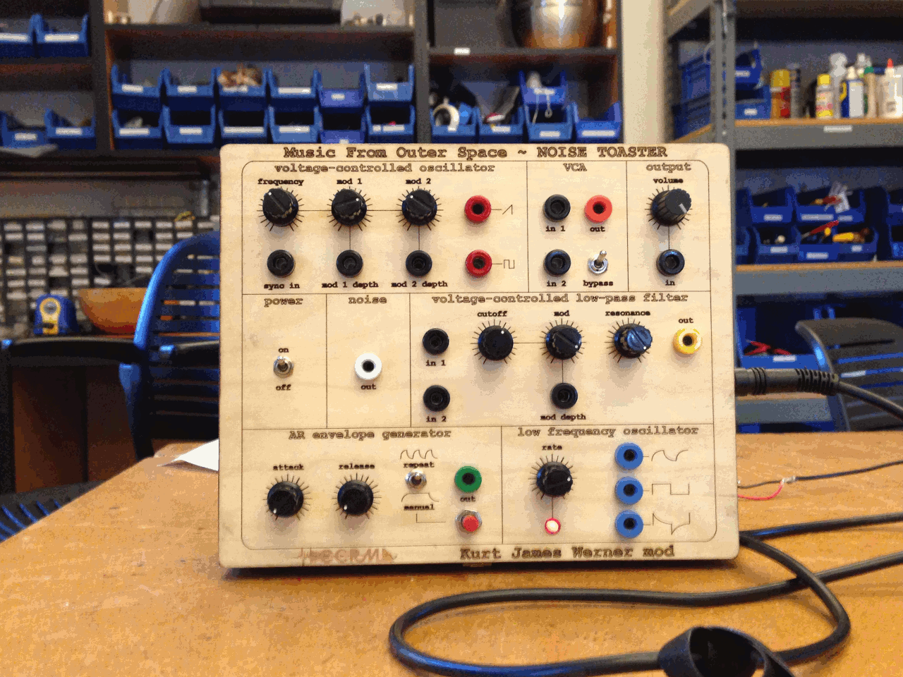
Front Panel Template (download .ai version)
I laser cut my front panel in Stanford's Product Realization Lab (PRL). It is 1/16" birch, laminated with wood epoxy onto the lid of a cigar box I bought for $5 at a cigar store on University Avenue (thanks to Sasha Leitman for the tip). It turns out this arrangement was a little too thick, and I had to countersink the potentiometers a little bit (Thanks to John Granzow and Nette Worthy for tips on this).

I designed this front panel in Adobe Illustrator by modifying Romain Michon's vectorized version of the Noise Toaster front panel from Ray's article. Click on the image above or "download .ai version" to download the Adobe Illustrator file and make your own (or modify).
Front Panel Wiring
Here's how I wired my front panel. The nodes are all labelled (X__) just like they are on the schematics. Note well that nodes "VCF" (the yellow banana jack) and "VCA2" don't appear on the original schematics, they are unique to this mod. I tried to respect the conventions that Ray used on his front panel wiring scheme, to make it easy to cross-check.

Here's what it looks like with just the front panel wired up:
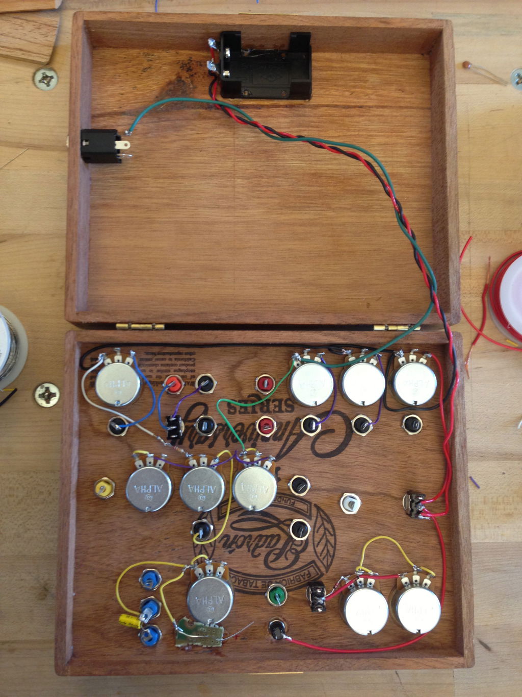
Here's what it looks like with the PCB wired in too (although without the speaker):

This build is probably not very well shielded. This could be improved by laminating tin foil or copper guitar shielding tape on the inside of the lid, and/or by using a star ground to ground the chassis of the potentiometers and switches.
My Build
If you're interested in seeing more about my build, I've been posting pictures and notes at my Tumblr: kurtjameswerner.tumblr.com/tagged/Noise-Toaster. This won't have any special info about my mod, just documentation of my work, some more pictures, and a couple of dead ends.
In action!
As part of CCRMA's 2013 Fall Concert at Bing Concert Hall, I performed "Toast and Jam" with my modified Music From Outer Space Noise Toaster as part of Ensemble AnaLocos (Fernando Lopez-Lezcano, Romain Michon, Tim O'Brien, Myles Borins, Gina Collecchia, and myself). Everyone performed with Noise Toaster synths (mine and Myles' built from my modifications), and Nando added additional oopmh with his "El Dinosaurio" synth.
Skip to 1:10:10 in the following video of the 2013 Fall Concert to experience "Toast and Jam:"
From the program notes: "Six Noise Toasters, each with 10 knobs to twist, 9 switches to throw (well, 10 if you count the on/off switch) and a button to push. Six humans moving all those controls in unexpected yet related ways. A bit of reverberation to spice things up. A computer (we have to have a computer, right?) that places those sounds inside an artificial soundscape in Bing. The result: a chaotically complex sound, noise and modulation world. The Ensemble AnaLocos (contraction of Analógicos Locos, roughly "Crazy Analogs") tries to keep them [under|out] of control in this directed improvisation. The old guy that seems to be out of place (the synthesizer of course) is El Dinosaurio, another analog synth built more than 30 years ago and still young at heart, sonically speaking. El Dinosaurio is maybe the inspiration that lead to 5 students (Romain, Tim, Myles, Gina & Kurt - in no particular order) synchronizing their "Independent Study" courses with Nando, finding this hardware project on their own, building them, and finally jamming together for a better world, or maybe just a noisier one (in a good way). A happy outcome."
If you have any questions, corrections, &c.,
please feel free to contact me at
kwerner@ccrma.stanford.edu
last updated : 6 December 2013