Next |
Prev |
Up |
Top
|
JOS Index |
JOS Pubs |
JOS Home |
Search
Another attractive second-order filter structure, based on the
``digital waveguide oscillator'' [1], is the
digital waveguide resonator (DWR):
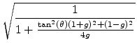
where4
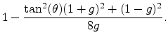
Note that
 when
when  (undamped case).
Like the MCF, the DWR produces steady sinusoidal oscillations
indefinitely, even for short word lengths. This happens because the
resonance tuning is controlled by only one coefficient, when the
damping goes to zero. As would be the case for any oscillator
structure which is controlled by one coefficient affecting tuning
only, quantization of that coefficient can only affect tuning as well.
Unlike the MCF and complex multiply, which require four multiplies per
sample, the DWR requires only two multiplies per sample. Moreover,
when the decay is set to
(undamped case).
Like the MCF, the DWR produces steady sinusoidal oscillations
indefinitely, even for short word lengths. This happens because the
resonance tuning is controlled by only one coefficient, when the
damping goes to zero. As would be the case for any oscillator
structure which is controlled by one coefficient affecting tuning
only, quantization of that coefficient can only affect tuning as well.
Unlike the MCF and complex multiply, which require four multiplies per
sample, the DWR requires only two multiplies per sample. Moreover,
when the decay is set to
 (
( ), one of the
multiplies in the DWR disappears, leaving only one multiply per
sample for sinusoidal oscillation. As a result, the DWR appears to be
best suited for VLSI implementation. As an added bonus, the
), one of the
multiplies in the DWR disappears, leaving only one multiply per
sample for sinusoidal oscillation. As a result, the DWR appears to be
best suited for VLSI implementation. As an added bonus, the  and
and
 outputs of the DWR are in exact phase quadrature, like the
complex-multiply case considered first above. Note, however, that the
choice of input (to either the
outputs of the DWR are in exact phase quadrature, like the
complex-multiply case considered first above. Note, however, that the
choice of input (to either the  or
or  state variables)
results different amplitude scaling.
state variables)
results different amplitude scaling.
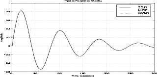
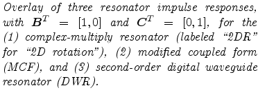
Figure 1 shows an overlay of initial impulse responses for
the three resonators discussed above. The decay factor was set to
 , and the output of each multiplication was quantized to 16
bits, as were all coefficients. The three waveforms sound and look
identical. (There are small differences, however, which can be
seen by plotting the differences of pairs of waveforms.)
, and the output of each multiplication was quantized to 16
bits, as were all coefficients. The three waveforms sound and look
identical. (There are small differences, however, which can be
seen by plotting the differences of pairs of waveforms.)
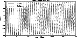
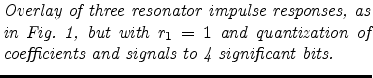
Figure 2 shows the same impulse-response overlay but with
and only 4 significant bits in the coefficients and signals.
The complex multiply oscillator can be seen to decay toward zero due
to coefficient quantization (
 ). The MCF and DWR remain
steady at their initial amplitude. All three suffer some amount of
tuning perturbation.
). The MCF and DWR remain
steady at their initial amplitude. All three suffer some amount of
tuning perturbation.
Next |
Prev |
Up |
Top
|
JOS Index |
JOS Pubs |
JOS Home |
Search
Download smac03maxjos.pdf