Next |
Prev |
Up |
Top
|
Index |
JOS Index |
JOS Pubs |
JOS Home |
Search
In lumped systems, traveling waves do not occur, in principle, because
lumped elements are characterized as one-ports interconnected by
``wires'' having no time delay associated with them. It may therefore
seem strange that a scattering theory formulation exists for lumped
networks.
There does exist, however, a physical interpretation of reflection and
transmission in lumped networks [33]. Suppose we have a
``force source''  which drives a ``load impedance''
  in
series with a ``source impedance''
in
series with a ``source impedance''  . For simplicity, let the
load and source impedances be real (dashpots) as shown in
Fig. J.15.
. For simplicity, let the
load and source impedances be real (dashpots) as shown in
Fig. J.15.
Figure J.15:
A
series connection of two dashpots and driven by a force
. Dashpot models the source impedance, while models
a load impedance.
![\includegraphics[width=3in]{eps/lparallel_dashpots}](img2575.png) |
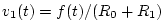
An equivalent electrical circuit is shown in
Fig. J.16.
Figure J.16:
Equivalent circuit of a dashpot driven by a force source
with internal impedance .
![\includegraphics[width=3in]{eps/lparallelDashpotsEqvCkt}](img2576.png) |
Then the velocity is given by
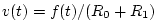 , and the ``force drop'' across the load is
The instantaneous power delivered to the load is therefore
If this expression is differentiated with respect to and set to zero
to find its maximizer, we find that maximum power is delivered when
, and the ``force drop'' across the load is
The instantaneous power delivered to the load is therefore
If this expression is differentiated with respect to and set to zero
to find its maximizer, we find that maximum power is delivered when
 , i.e., in the matched impedance case.J.5 The force on the load at matched impedance is
  ,
and the power delivered is
which is called the maximum available power from a force
through a source impedance . Define the ``matched velocity''
in the matched impedance case as
The relative difference between the matched velocity
,
and the power delivered is
which is called the maximum available power from a force
through a source impedance . Define the ``matched velocity''
in the matched impedance case as
The relative difference between the matched velocity  and any
other velocity
and any
other velocity
 delivered to an unmatched
load is given by
This is the formula for the reflection coefficient seen at the
junction of two waveguides (or transmission lines), where one
waveguide has impedance and the other has impedance . In
this context, multiplying the maximum available power velocity
delivered to an unmatched
load is given by
This is the formula for the reflection coefficient seen at the
junction of two waveguides (or transmission lines), where one
waveguide has impedance and the other has impedance . In
this context, multiplying the maximum available power velocity  by the reflection coefficient
  gives the difference between
and the velocity actually delivered. This difference can be
interpreted as reflected power. Conceptually, the driving
force ``sends'' maximum available power, and the load ``reflects
back'' some of it, unless the load impedance matches the source
impedance, and this transaction occurs instantaneously. Thus, the
wave variable reflection coefficient in lumped systems can be thought
of as the coefficient of velocity reflection relative to the velocity
at maximum available power. A similar calculation shows that the
force reflection coefficient is
gives the difference between
and the velocity actually delivered. This difference can be
interpreted as reflected power. Conceptually, the driving
force ``sends'' maximum available power, and the load ``reflects
back'' some of it, unless the load impedance matches the source
impedance, and this transaction occurs instantaneously. Thus, the
wave variable reflection coefficient in lumped systems can be thought
of as the coefficient of velocity reflection relative to the velocity
at maximum available power. A similar calculation shows that the
force reflection coefficient is  , and the reflection
coefficient for signal power itself is
, and the reflection
coefficient for signal power itself is  .
.
Next |
Prev |
Up |
Top
|
Index |
JOS Index |
JOS Pubs |
JOS Home |
Search
[How to cite and copy this work]