Next  |  Prev  |  Up  |  Top  |  Index  |  JOS Index  |  JOS Pubs  |  JOS Home  |  Search


Example Tapped Delay Line

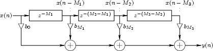
An example of a TDL with two internal taps is shown in Fig. 1.13. The total delay line length is $ M_3$ samples, and the internal taps are located at delays of $ M_1$ and $ M_2$ samples, respectively. The output signal is a linear combination of the input signal $ x(n)$, the delay-line output $ x(n-M_3)$, and the two tap signals $ x(n-M_1)$ and $ x(n-M_2)$.

Figure 1.13: Tapped Delay Line (TDL).
\begin{figure}\input fig/tdl.pstex_t
\end{figure}

The difference equation of the TDL in Fig. 1.13 is, by inspection,

$\displaystyle y(n) = b_0 x(n) + b_{M_1} x(n-M_1) + b_{M_2} x(n-M_2) + b_{M_3} x(n-M_3)
$

corresponding to the transfer function

$\displaystyle H(z) = b_0 + b_{M_1} z^{-M_1} + b_{M_2} z^{-M_2} + b_{M_3} z^{-M_3}
$


Next  |  Prev  |  Up  |  Top  |  Index  |  JOS Index  |  JOS Pubs  |  JOS Home  |  Search

[How to cite and copy this work] 
``Physical Audio Signal Processing for Virtual Musical Instruments and Digital Audio Effects'', by Julius O. Smith III, (December 2005 Edition).
Copyright © 2006-07-01 by Julius O. Smith III
Center for Computer Research in Music and Acoustics (CCRMA),   Stanford University
CCRMA  [Automatic-links disclaimer]