Next |
Prev |
Up |
Top
|
Index |
JOS Index |
JOS Pubs |
JOS Home |
Search
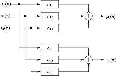
Figure 2.1 depicts the general reverberation scenario for three
sources and one listener (two ears). In general, the filters should
also include filtering by the pinnae
of the ears, so that each echo can be perceived as coming from the
correct angle of arrival in 3D space; in other words, at least some
reverberant reflections should be spatialized so that they
appear to come from their natural directions in 3D space
[233]. Again, the filters change if anything changes in
the listening space, including source or listener position. All
prevalent artificial reverberation systems implement some
approximation of the system in Fig. 2.1.
Figure 2.1:
General reverberation simulation for three sources
and one listener (two ears). Each filter  can be implemented
as a tapped delay line FIR filter.
can be implemented
as a tapped delay line FIR filter.
 |
In the frequency domain, it is convenient to express the input-output relationship
in terms of the transfer-function matrix:
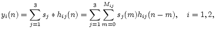
Denoting the impulse response of the filter from source  to ear
  by
by  , the two output signals in Fig. 2.1 are computed by
six convolutions:
, the two output signals in Fig. 2.1 are computed by
six convolutions:
where  denotes the order of FIR filter . Since many
of the filter coefficients are zero (at least for small
denotes the order of FIR filter . Since many
of the filter coefficients are zero (at least for small
 ), it is more efficient to implement them as tapped delay
lines (§1.5)
so that the inner sum becomes sparse.
For greater accuracy, each tap may include a lowpass
filter which models air absorption [294] and/or
spherical spreading loss (see §1.3).
For large ,
the impulse responses are not sparse, and we must either implement
very expensive FIR filters, or approximate the tail of the impulse
response using less expensive IIR filters; this subject--``late
reverberation'' approximation--is taken up in §2.4.
), it is more efficient to implement them as tapped delay
lines (§1.5)
so that the inner sum becomes sparse.
For greater accuracy, each tap may include a lowpass
filter which models air absorption [294] and/or
spherical spreading loss (see §1.3).
For large ,
the impulse responses are not sparse, and we must either implement
very expensive FIR filters, or approximate the tail of the impulse
response using less expensive IIR filters; this subject--``late
reverberation'' approximation--is taken up in §2.4.
Next |
Prev |
Up |
Top
|
Index |
JOS Index |
JOS Pubs |
JOS Home |
Search
[How to cite and copy this work]
![$\displaystyle \left[\begin{array}{c} Y_1(z) \\ [2pt] Y_2(z) \end{array}\right] ...
...left[\begin{array}{c} S_1(z) \\ [2pt] S_2(z) \\ [2pt] S_3(z)\end{array}\right]
$](img371.png)