
Define the reflection coefficient of the scattering junction as
Then we get the following scattering relations in terms of
![\begin{eqnarray*}
p^+_2 &=& (1+\rho)p^+_1\\ [3pt]
p^-_1 &=& \rho\,p^+_1
\end{eqnarray*}](img3542.png)
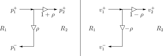
Signal flow graphs for pressure and velocity are given in Fig.C.16.
 |
It is a simple exercise to verify that signal power is conserved by
checking that
![]() .
(Left-going power is negated to account for its opposite
direction-of-travel.)
.
(Left-going power is negated to account for its opposite
direction-of-travel.)
So far we have only considered a plane wave incident on the left of
the junction. Consider now a plane wave incident from the right. For
that wave, the impedance steps from ![]() to
to ![]() , so the reflection
coefficient it ``sees'' is
, so the reflection
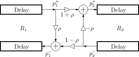
coefficient it ``sees'' is ![]() . By superposition, the signal flow
graph for plane waves incident from either side is given by
Fig.C.17. Note that the transmission coefficient is
one plus the reflection coefficient in either direction. This signal
flow graph is often called the ``Kelly-Lochbaum'' scattering junction
[299].
. By superposition, the signal flow
graph for plane waves incident from either side is given by
Fig.C.17. Note that the transmission coefficient is
one plus the reflection coefficient in either direction. This signal
flow graph is often called the ``Kelly-Lochbaum'' scattering junction
[299].
 |
There are some simple special cases: