Electronics
The laser emitter circuit:
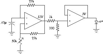
The laser emitter was extracted from a normal laser pointer we bought
at Fry's. The emitter is driven using a square oscillator going between
-3V and +3V. The output of the oscillator is fed through a buffer since
we don't know very much about the emitter (how much current it draws, what
its resistance is, etc). The frequency of the oscillator can be adjusted
to make the laser pulsing visible.
The laser detector circuit:
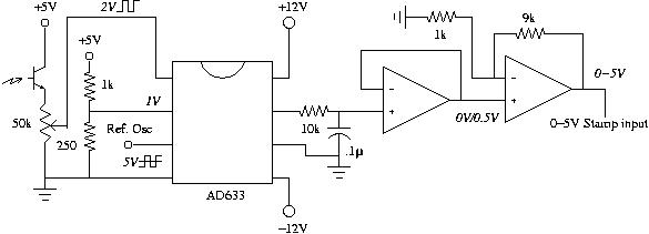
The detector circuit consists of 2 main parts: a voltage multiplier and an
optical sensor (
NTE3034A,
a T-NPN photo-darlington, also from Fry's). The
sensor will draw current when light falls on it. It is pretty insensitive
to ambient light and detects visible and near-infrared light. When we
point the modulated laser light from the emitter to it, we get a square
wave signal out of the emitter pin of the sensor (we connect the collector
to +5V). We need to adjust this voltage such that it goes between 0 and
+2V. The square wave detected by the sensor is fed to an
AD633,
a voltage multiplier. The reference voltage for this 0-2V square wave is
1V, such that the multiplier actually sees a square wave from -1V to
+1V. If we now feed the other input of the multiplier with the signal we
used to modulate the emitter (we scale it to be between -5V and +5V, using
a voltage divider), we will get a +0.5V DC signal out (the multiplier
multiplies signals and divides the result by 10V) only if the frequencies
of the input signals are equal. If there are small phase differences
between the signals, we can get short voltage drops in the DC signal,
which we counter by lowpass-filtering the output of the multiplier (160Hz
cutoff frequency, since you can't really move your hand that fast :-)
The output of the lowpass filter then goes to a positive gain amplifier
to create a +5V DC signal, which we can feed directly into the basic stamp
without using an A/D (the button command will do just fine).