Embedded DSP With Faust Workshop
Making Low Latency Guitar Pedals and Synthesizer Modules
July 22-26, 2019 — CCRMA, Stanford University
About
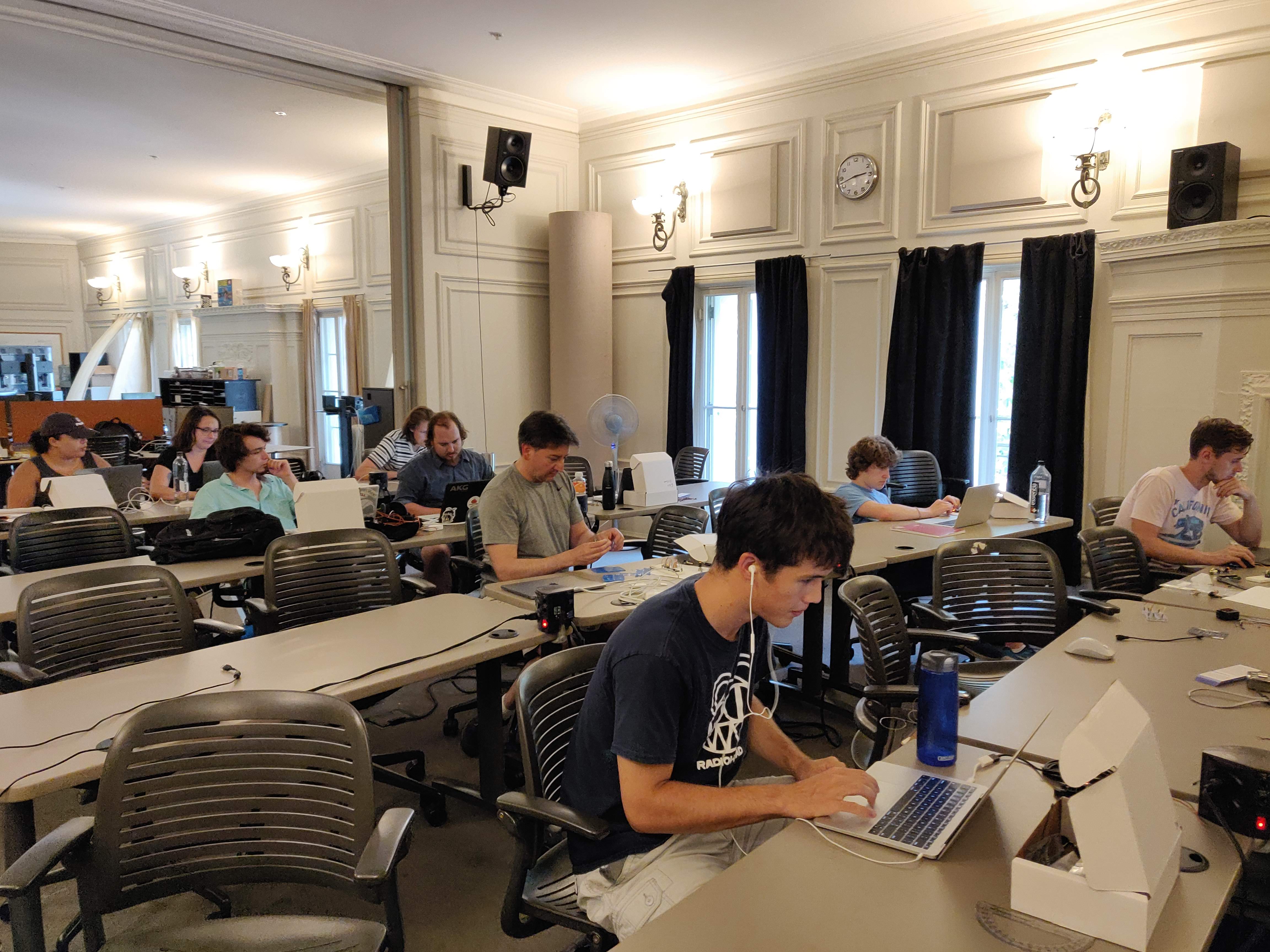
During this five day workshop (July 22-26, 2019 — CCRMA, Stanford University), participants learned how to program microcontrollers with the Faust programming language for bare-metal high efficiency/low latency real-time audio Digital Signal Processing (DSP). Final projects consisted of hardware for musical applications such as digital guitar pedal effects and synthesizer modules.
The Teensy 3.6 board was used as the main development platform. Its ARM Cortex-M4 microcontroller provides plenty of processing power to implement advanced DSP algorithms (e.g., feedback delay networks, physical models, band-limited oscillators, filter banks, etc.). Also, its various analog and digital inputs can be used for sensors acquisition. The lack of Operating System allows for the use of very low block sizes (i.e., 8 samples) offering extremely low audio latency.
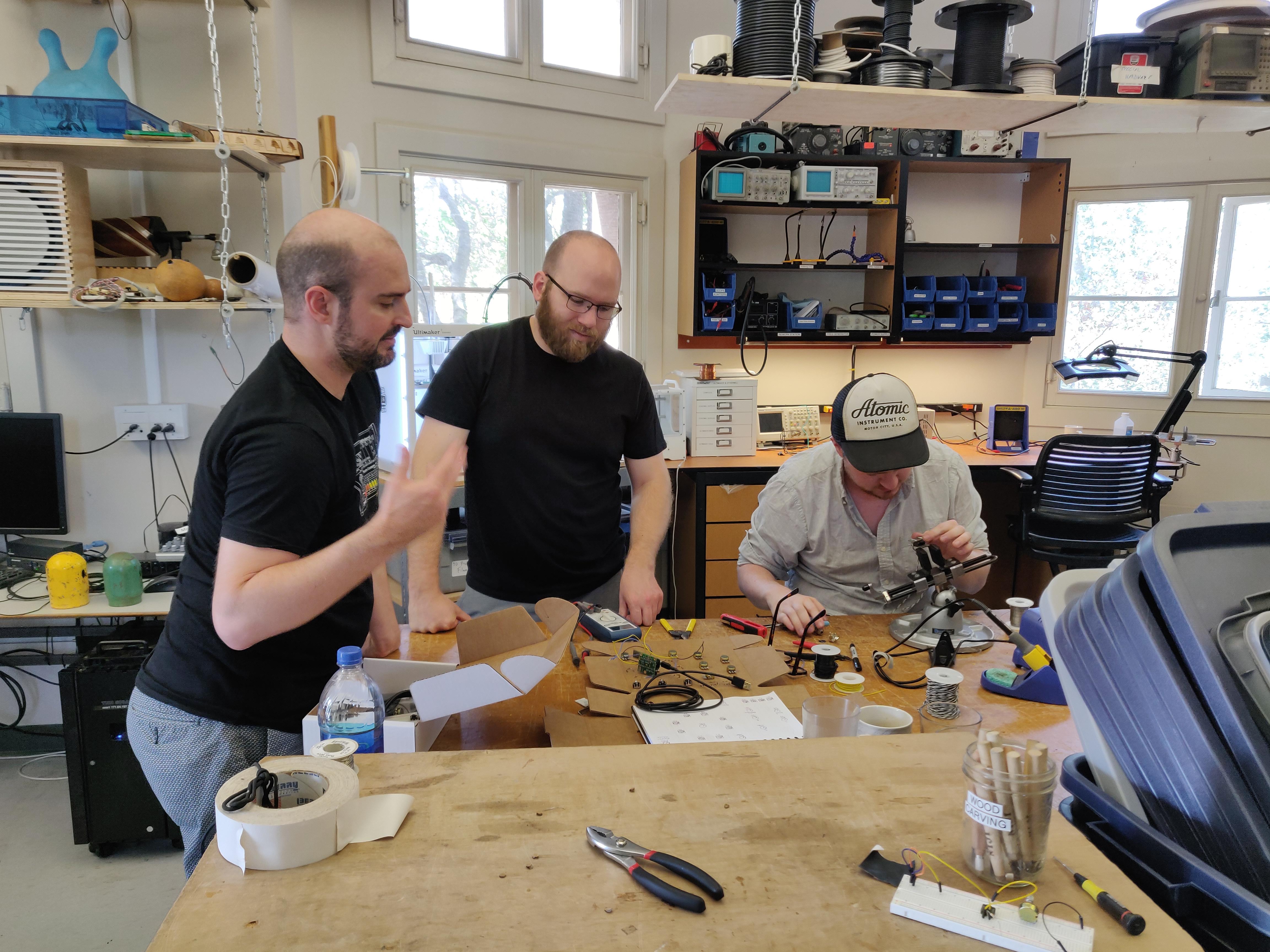
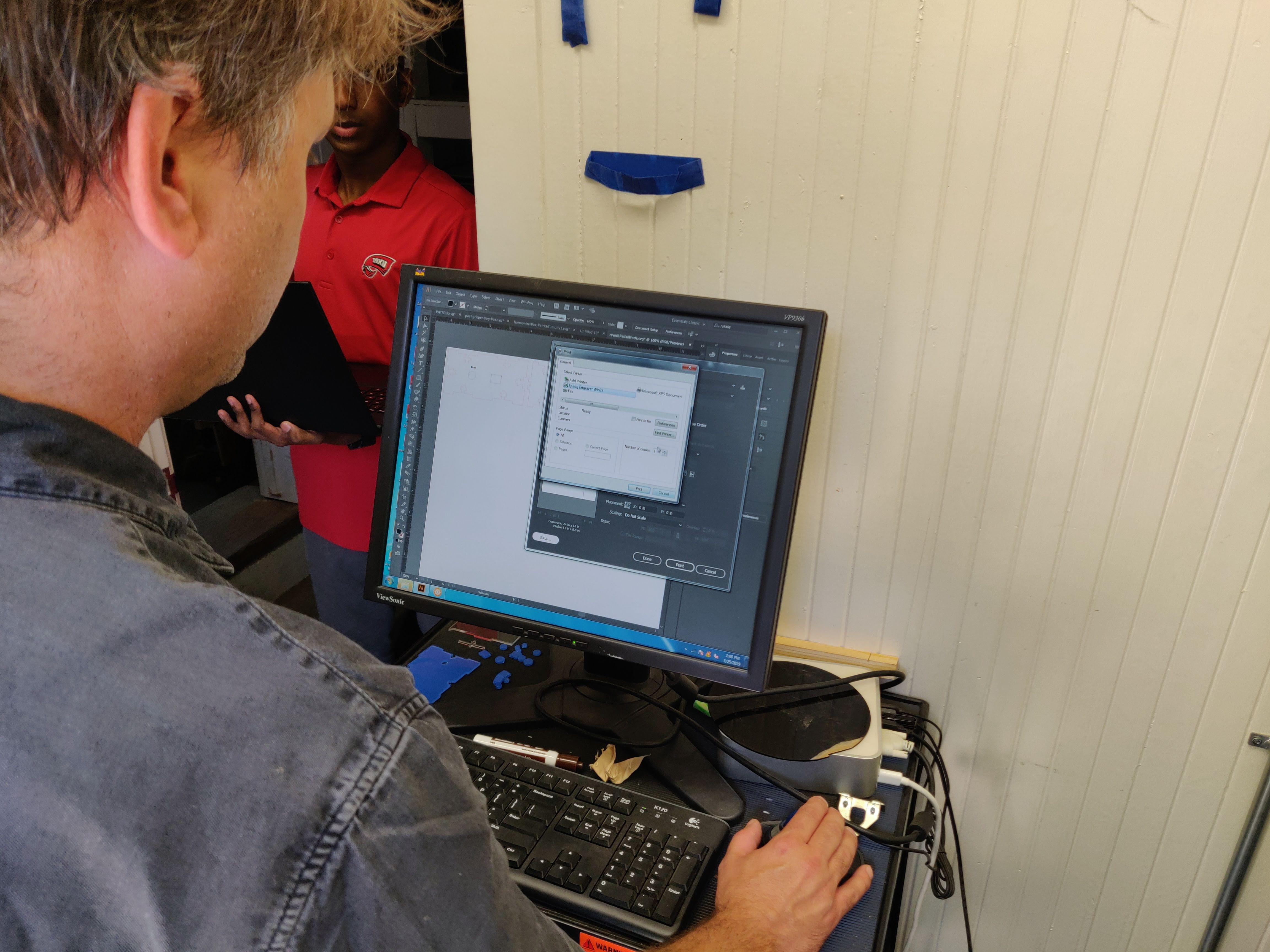
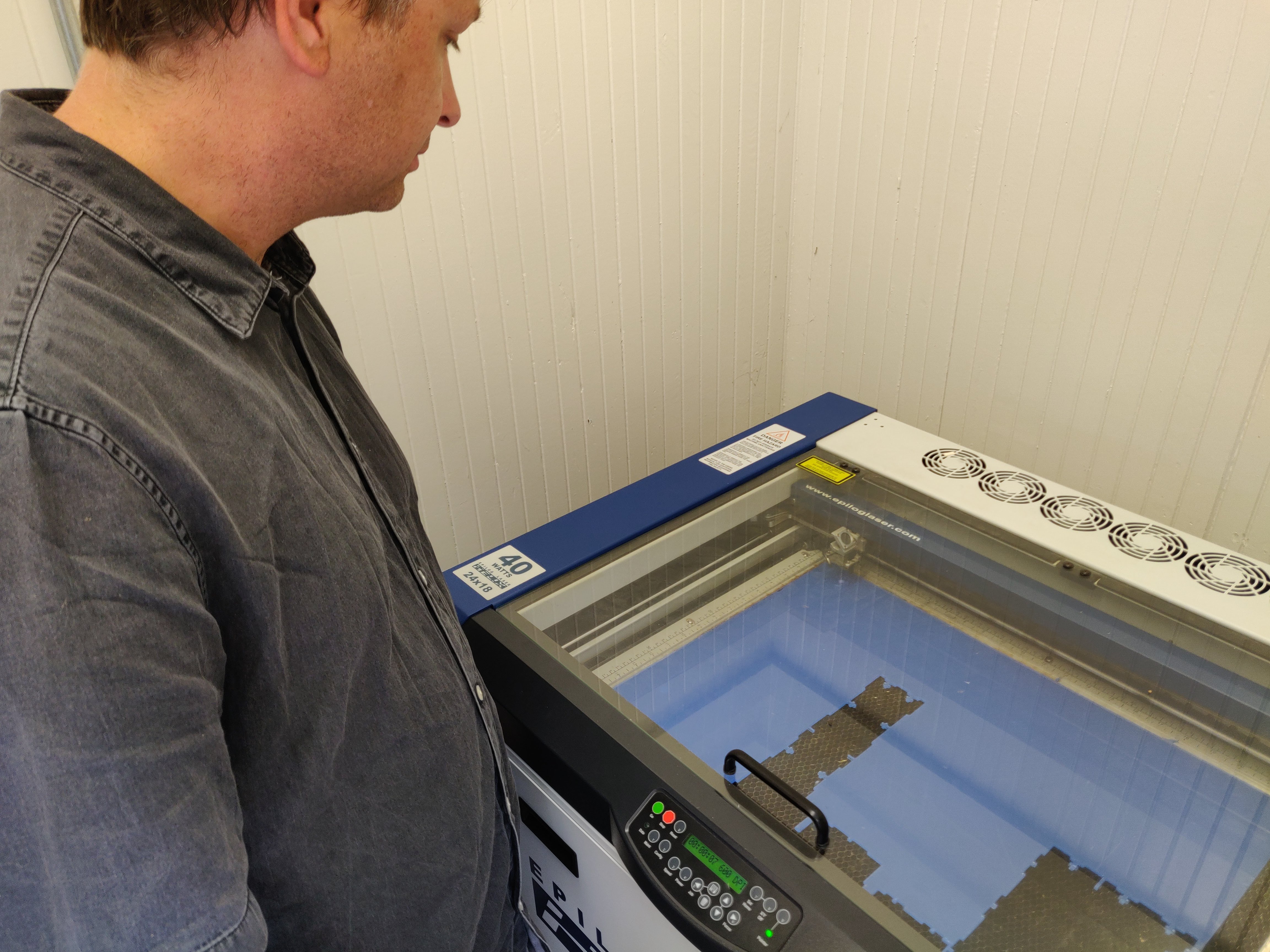
The focus of the workshop was on designing guitar pedal effects or synthesizer modules. To integrate this work into a final enclosure, students had access to the CCRMA prototyping lab ("MaxLab") where they learned how to make bespoke enclosures for their electronics using digital fabrication techniques (e.g., 2D CAD modeling, laser cutting, etc.).
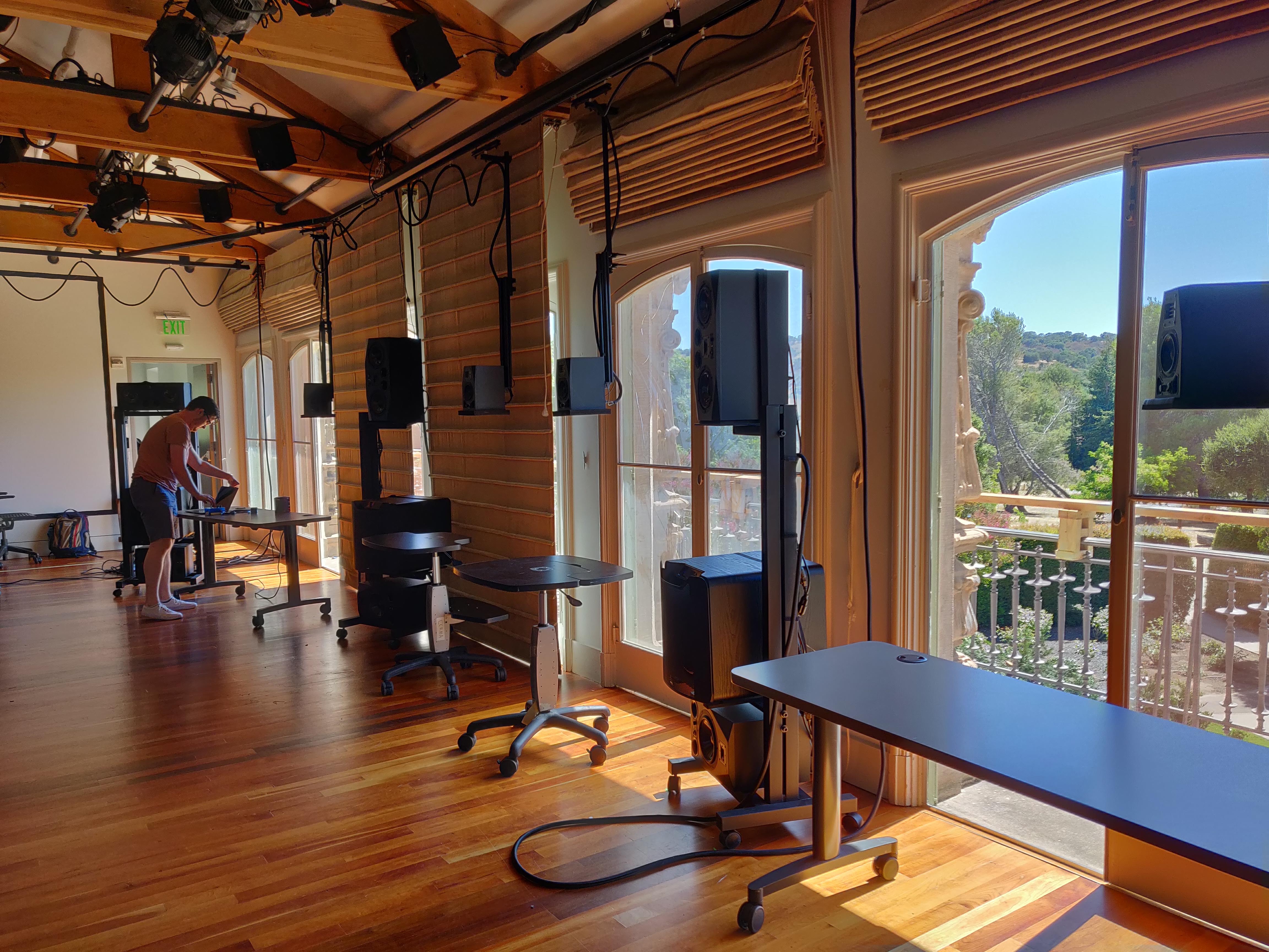
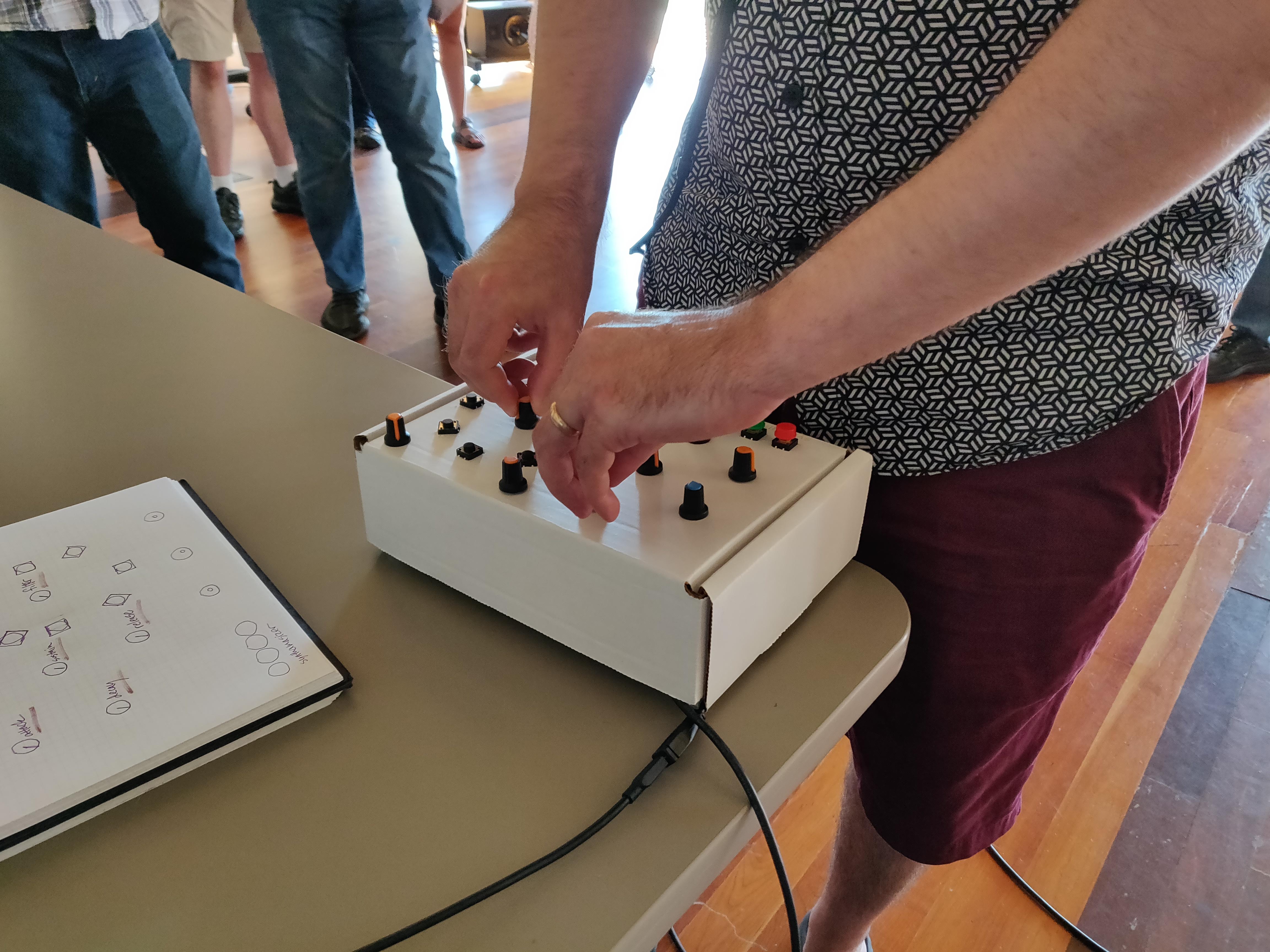
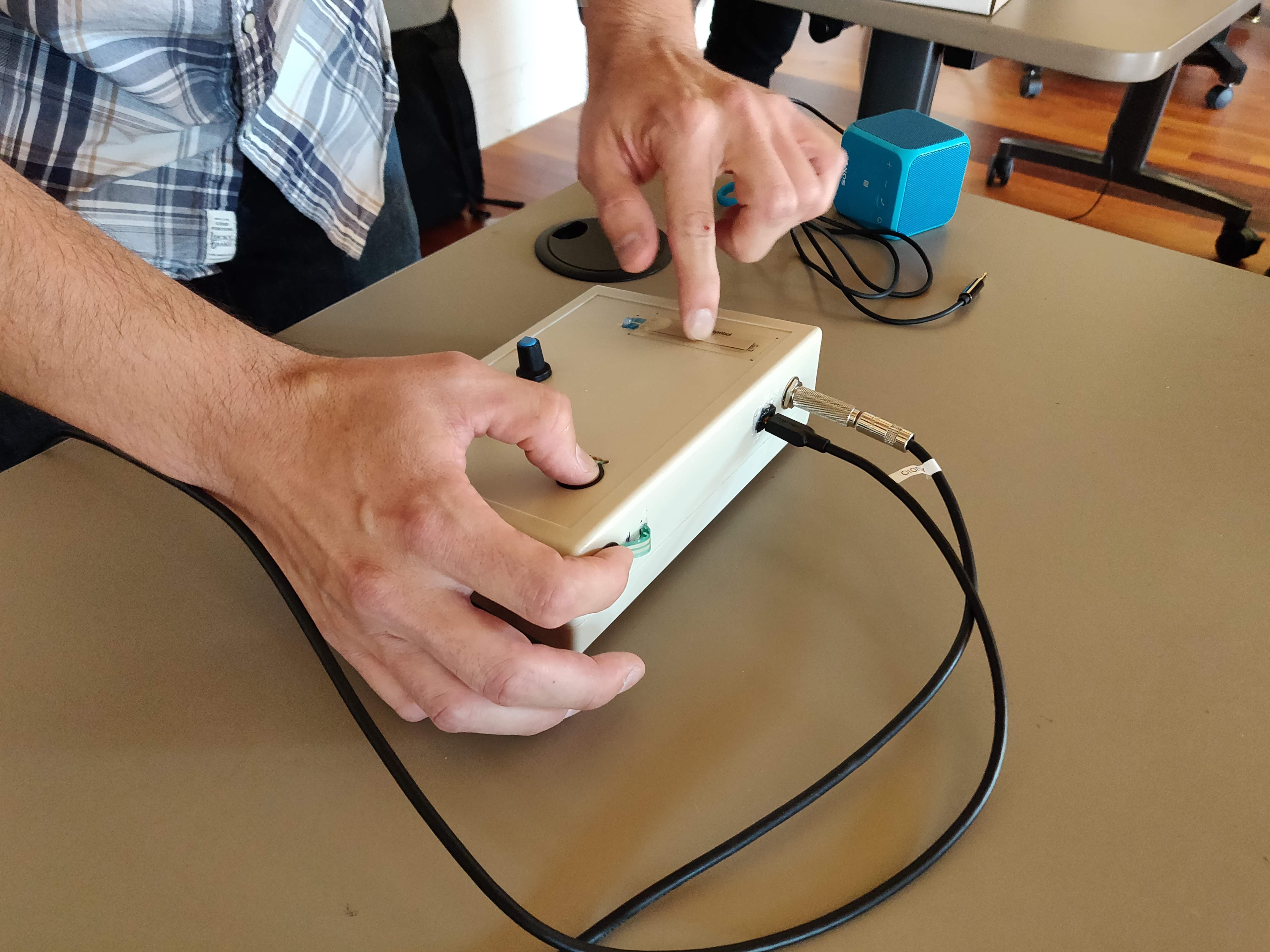
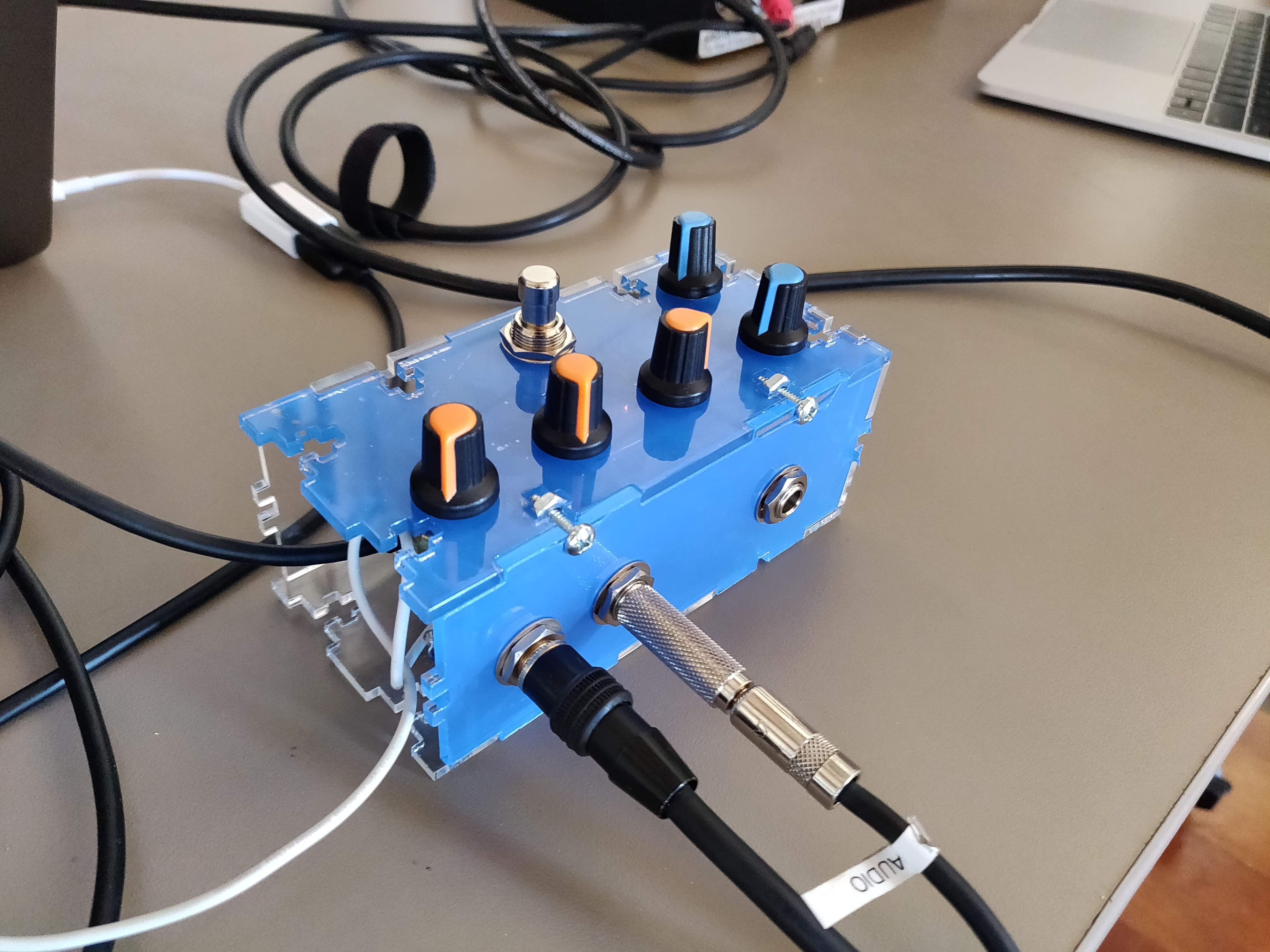
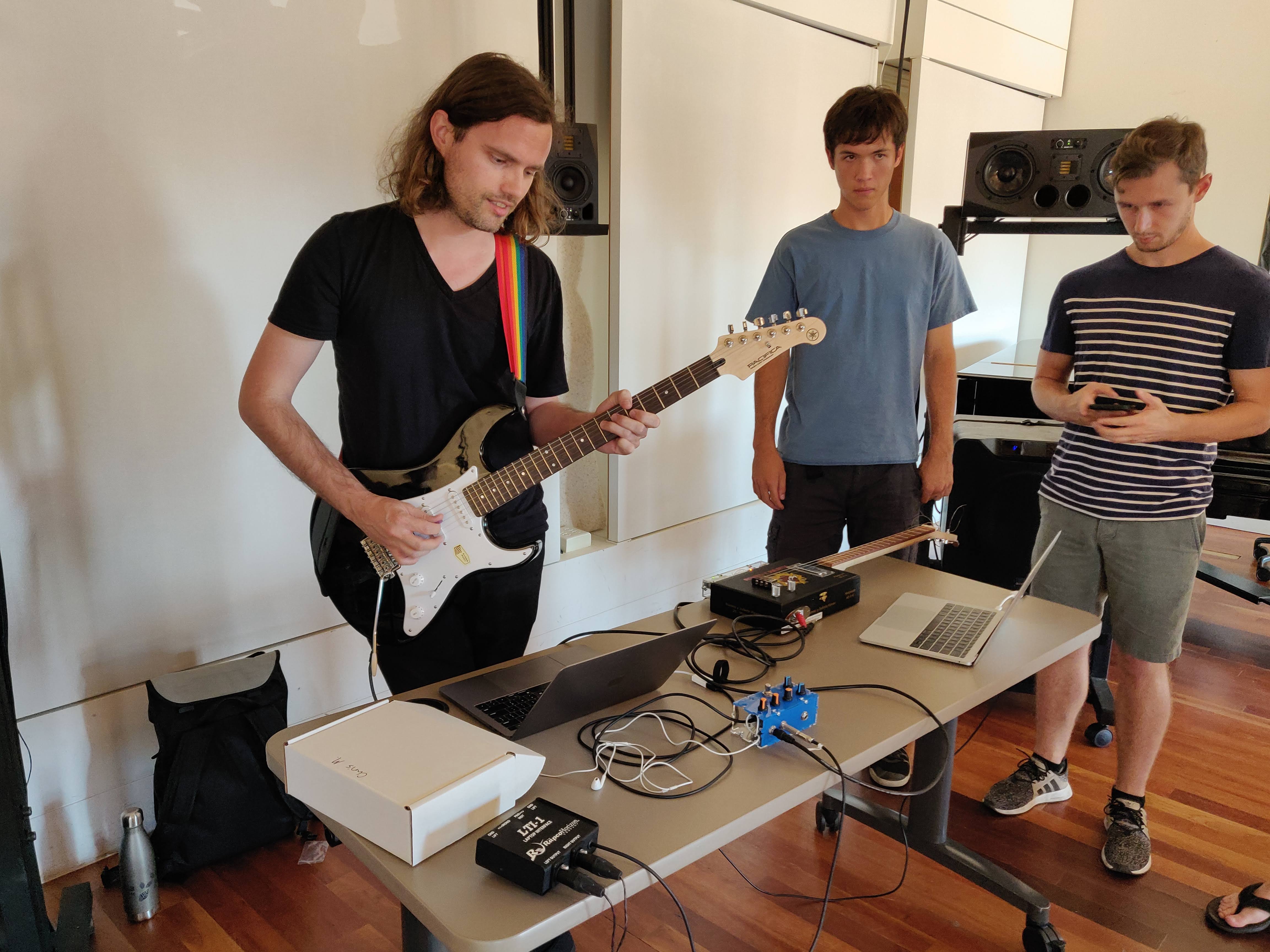
Student projects were featured during a showcase on the CCRMA stage at the end of the workshop.
Covered Topics
- Faust programming
- Digital Signal Processing for sound synthesis and audio effects (i.e., band-limited oscillators, filters, tremolo, physical modeling, reverb, chorus, flanger, phaser, distortion, echo, etc.)
- Fundamentals of low-level/bare-metal embedded audio signal processing
- 2D CAD modeling (i.e, OpenScad, Inkscape, etc.)
- Laser cutting
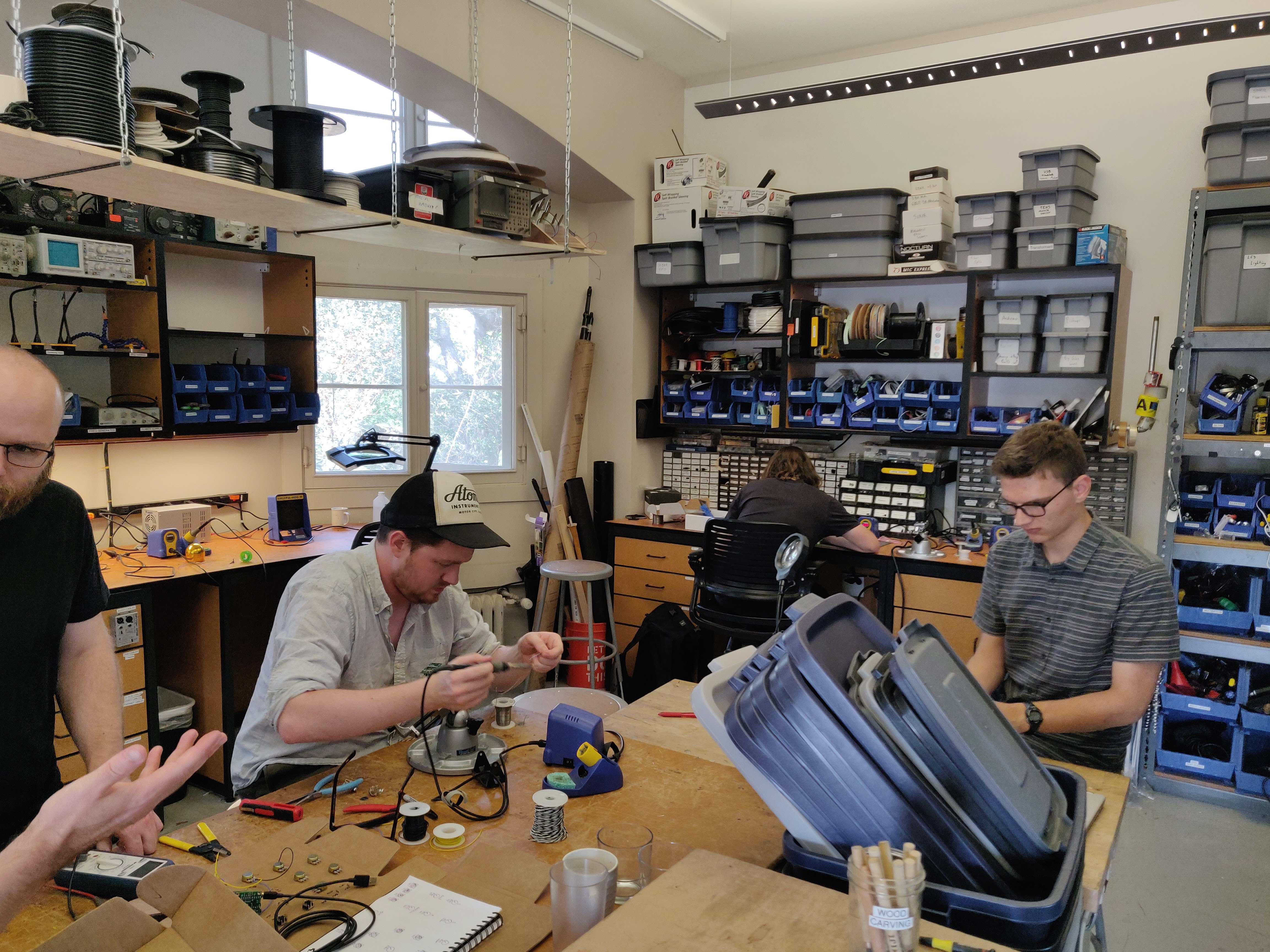
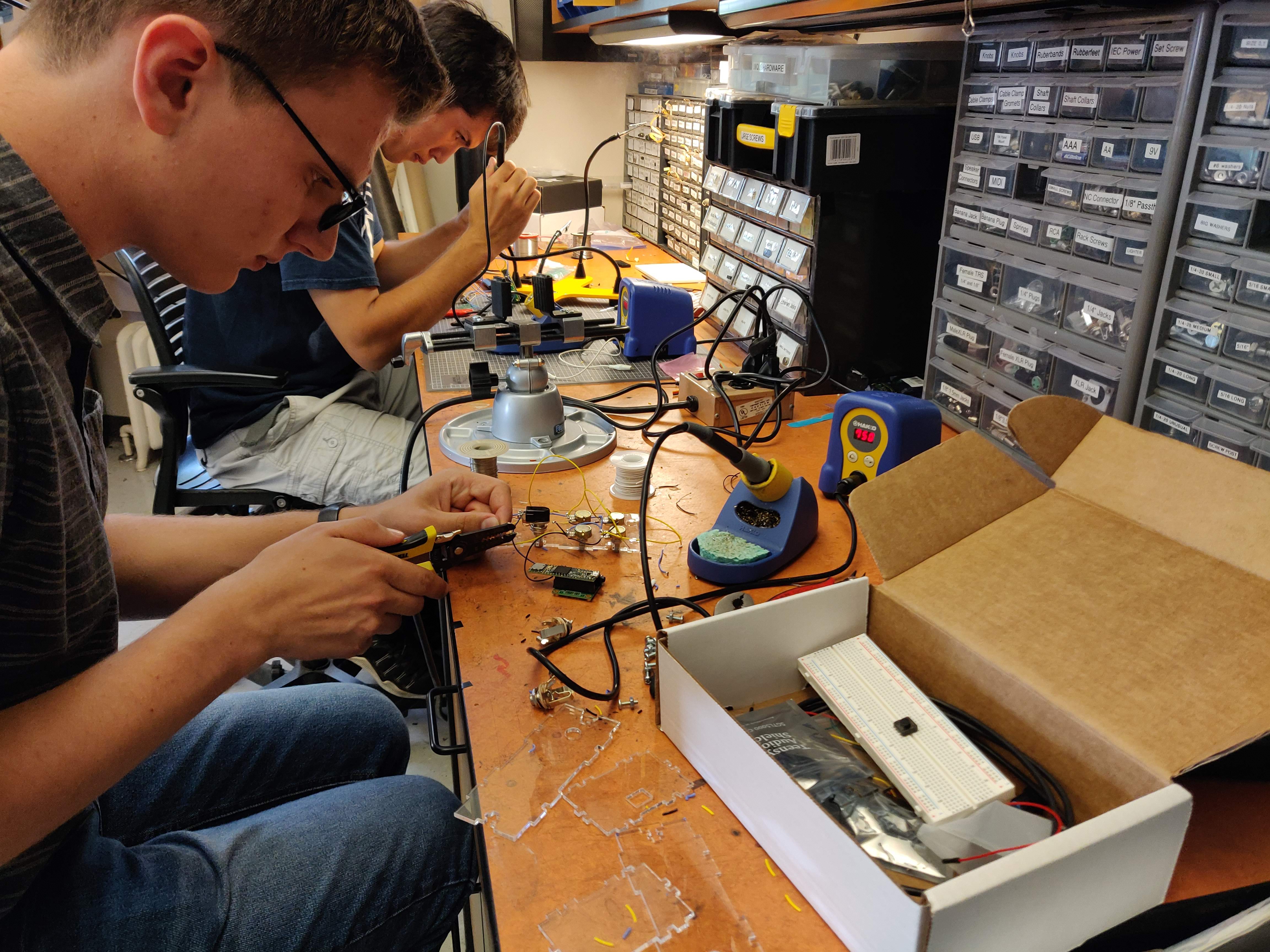
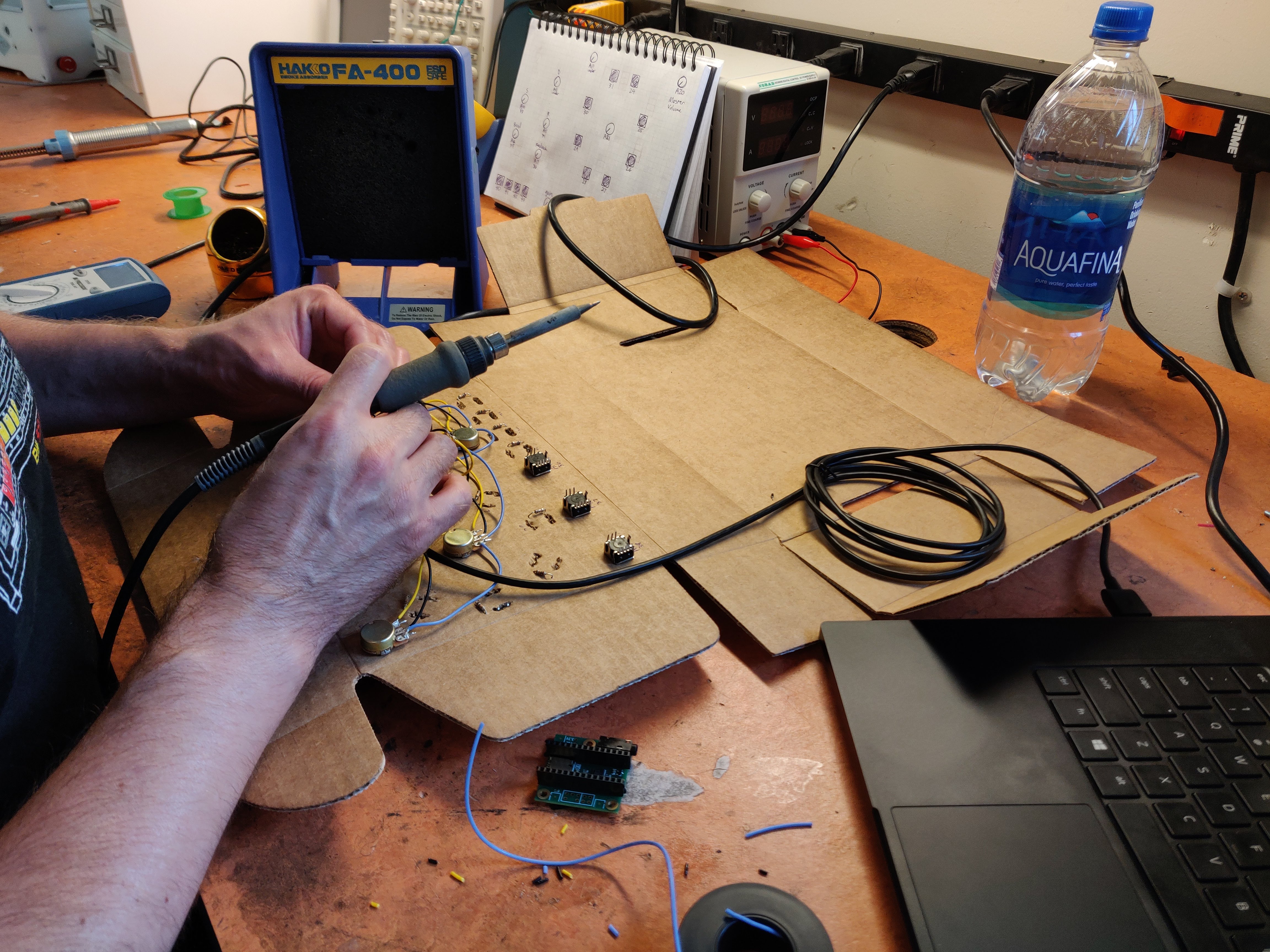
- Basic electronics/sensors (i.e., circuit design, soldering, knobs, buttons, switches, etc.)
Instructors
- Romain Michon — Researcher and Lecturer — GRAME-CNCM, Lyon (France) & CCRMA, Stanford University (USA)
- John Granzow — Assistant Professor — University of Michigan (USA)
Lab Kit
The workshop registration fee included a $100 lab kit containing all the required elements (i.e., microcontroller, audio codec, electronic components, casing, etc.) to build your own modular synth module, guitar pedal, etc. Each participant left with his own custom piece of hardware!
Additional Information
This workshop is intended for musicians, makers, engineers, computer scientists, etc. Previous background in computer programming and sound synthesis/processing is preferred but not mandatory. Participants should bring their own laptop. A lab kit fee of $100 will be added to the regular registration fee. Lab kits will include all the necessary elements to complete final projects (e.g., Teensy 3.6, Audio CODEC/Shield, knobs, switches, buttons, plastic for laser cutting, misc electronic components, cabling/wiring, etc.). Feel free to contact the workshop instructors for additional information.
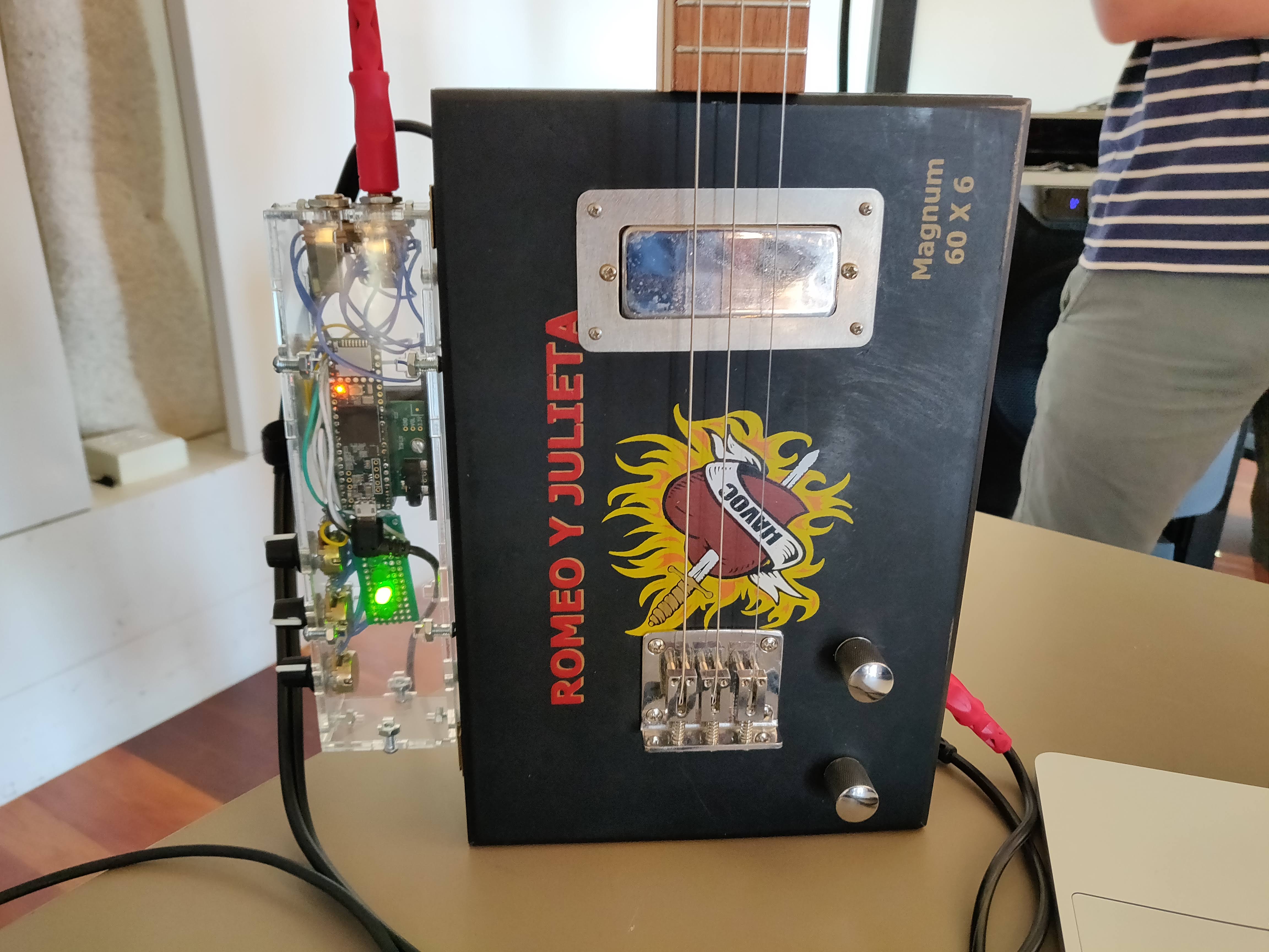
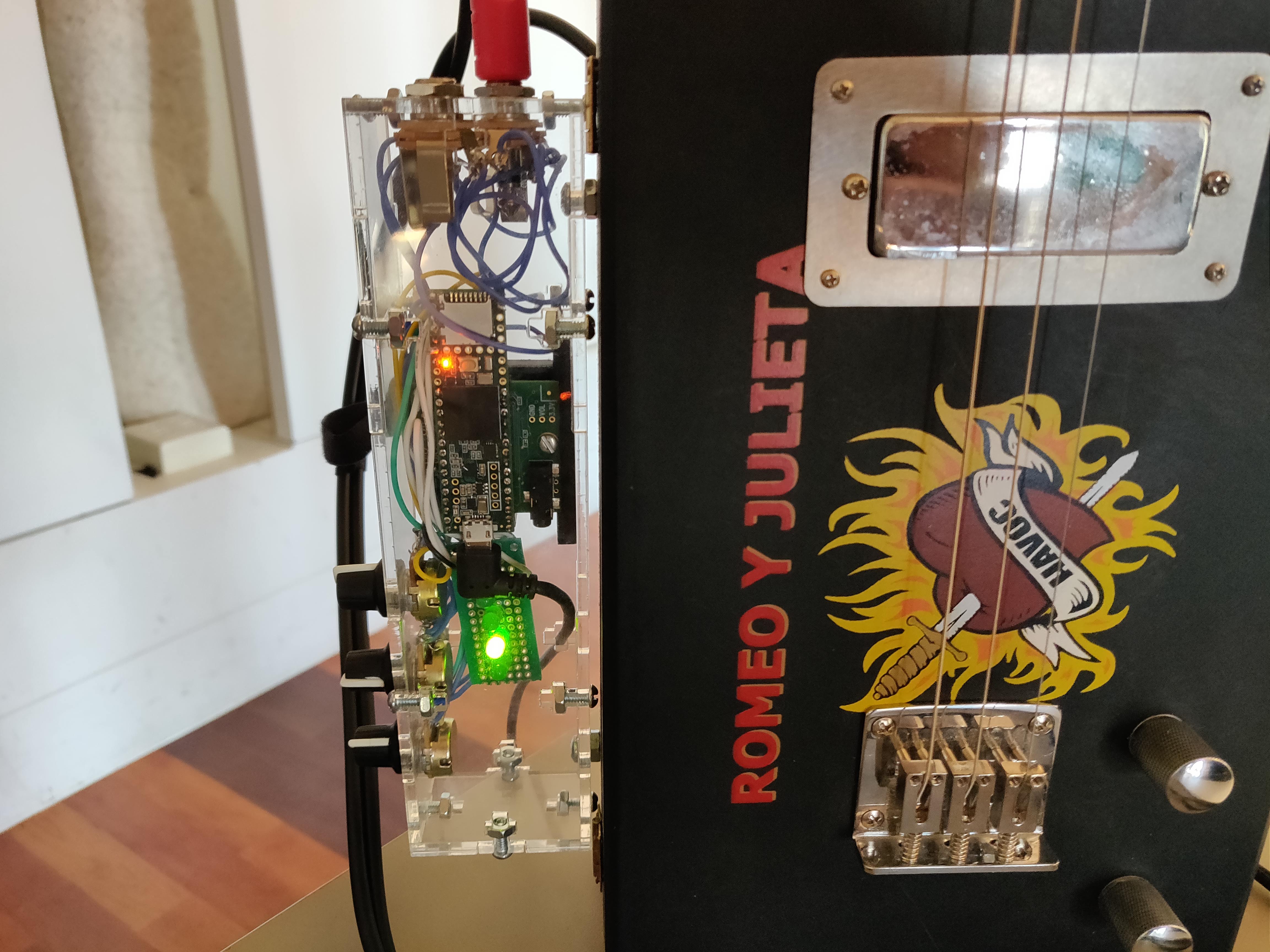
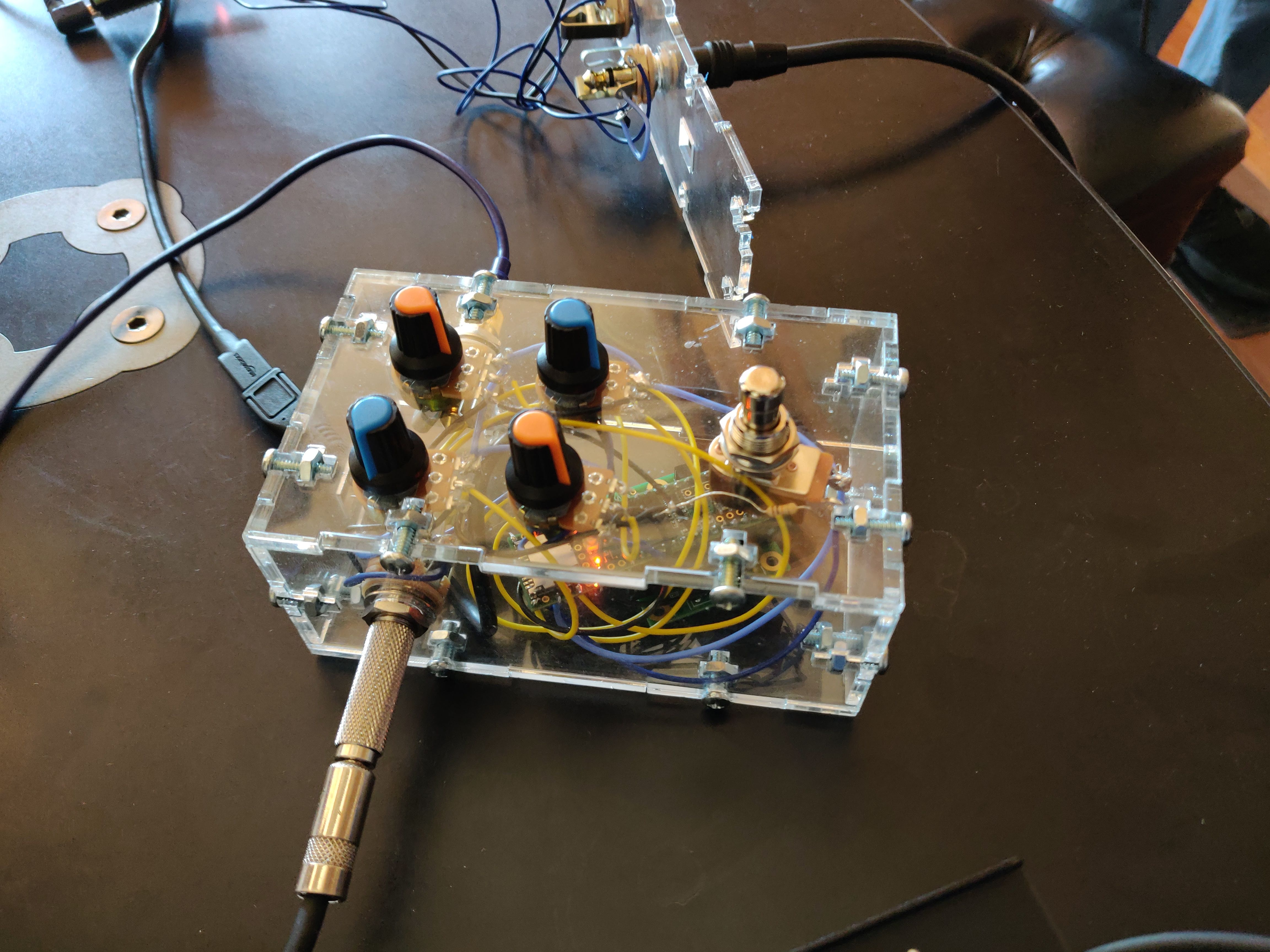
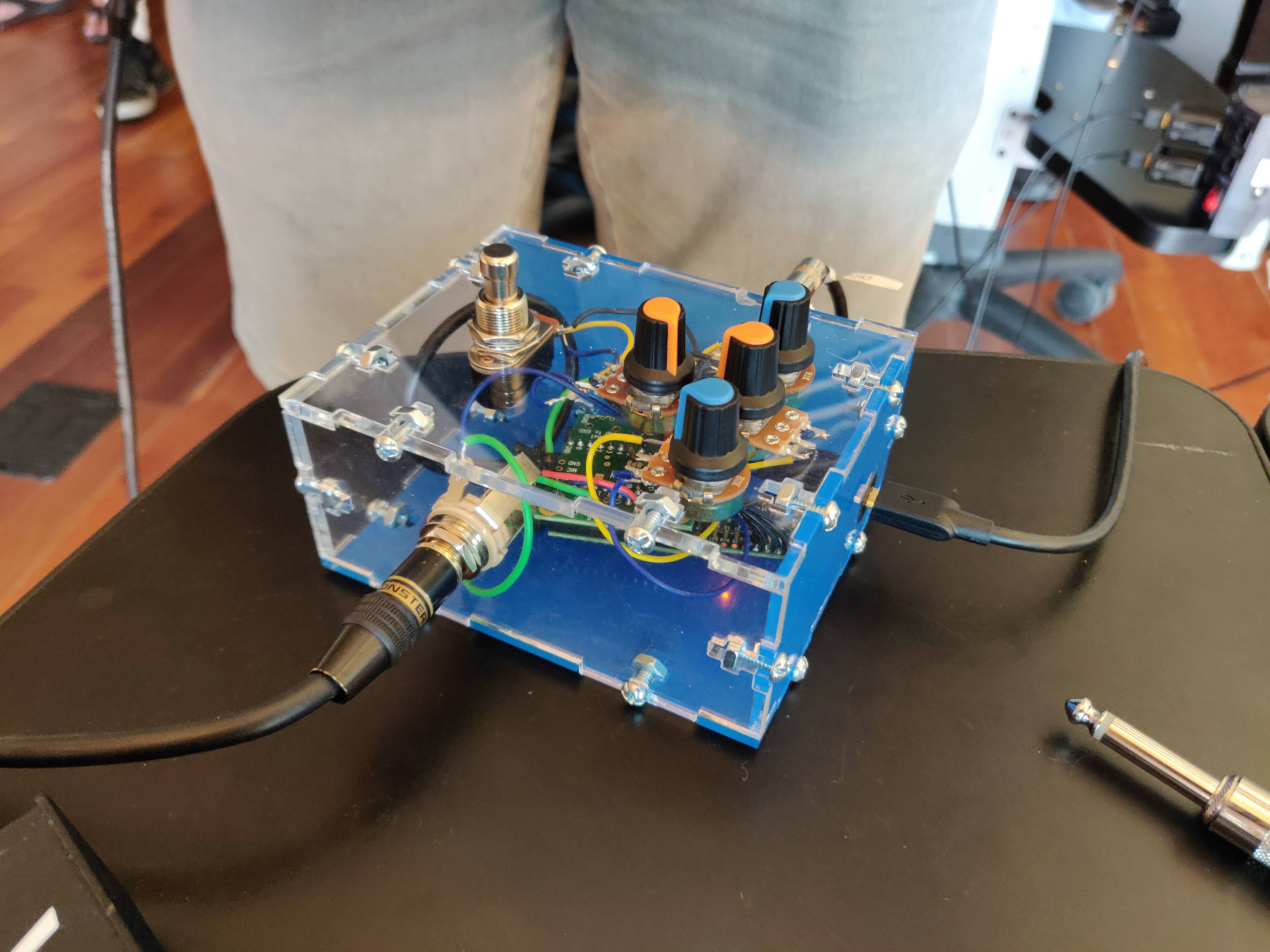
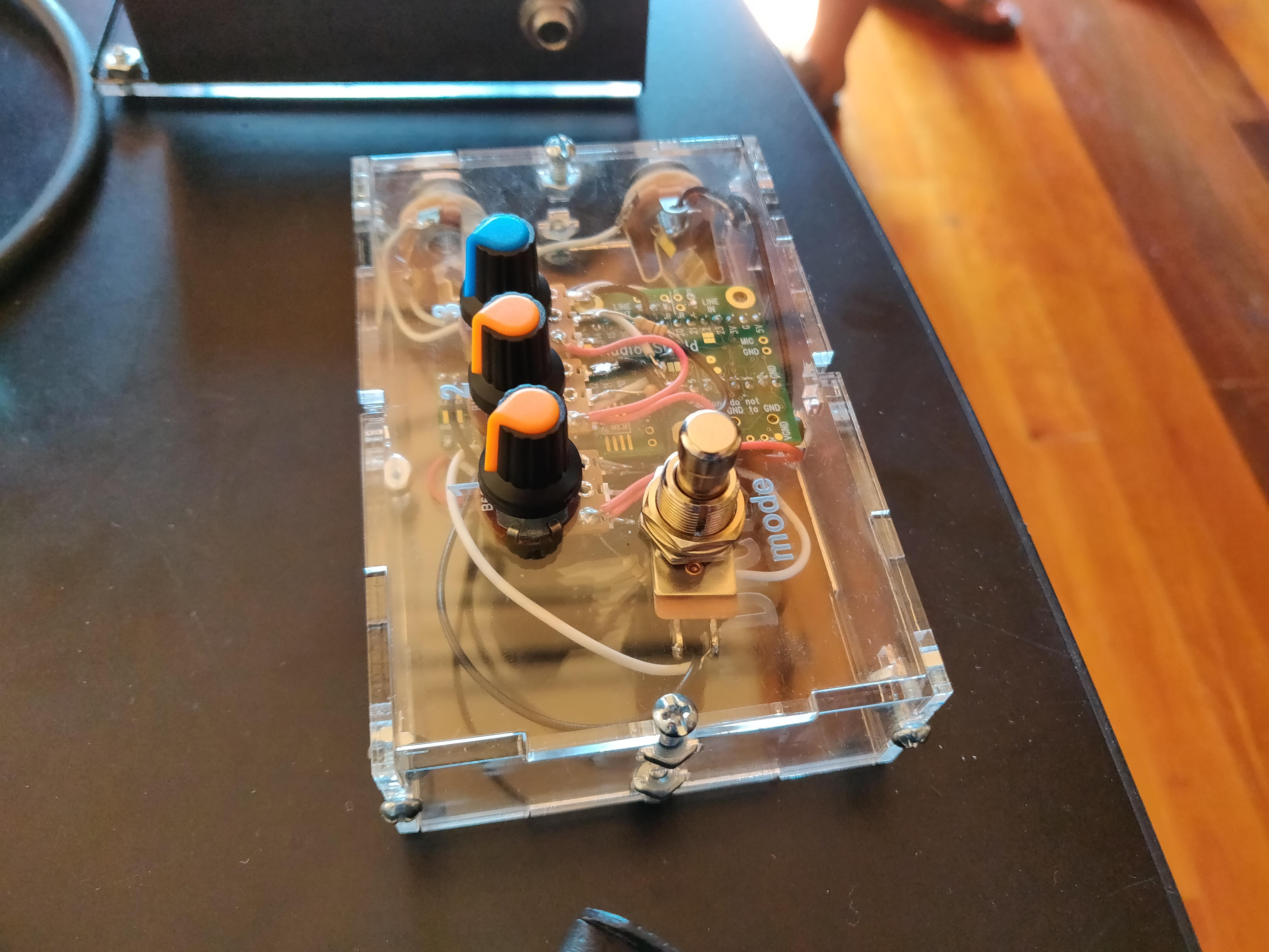
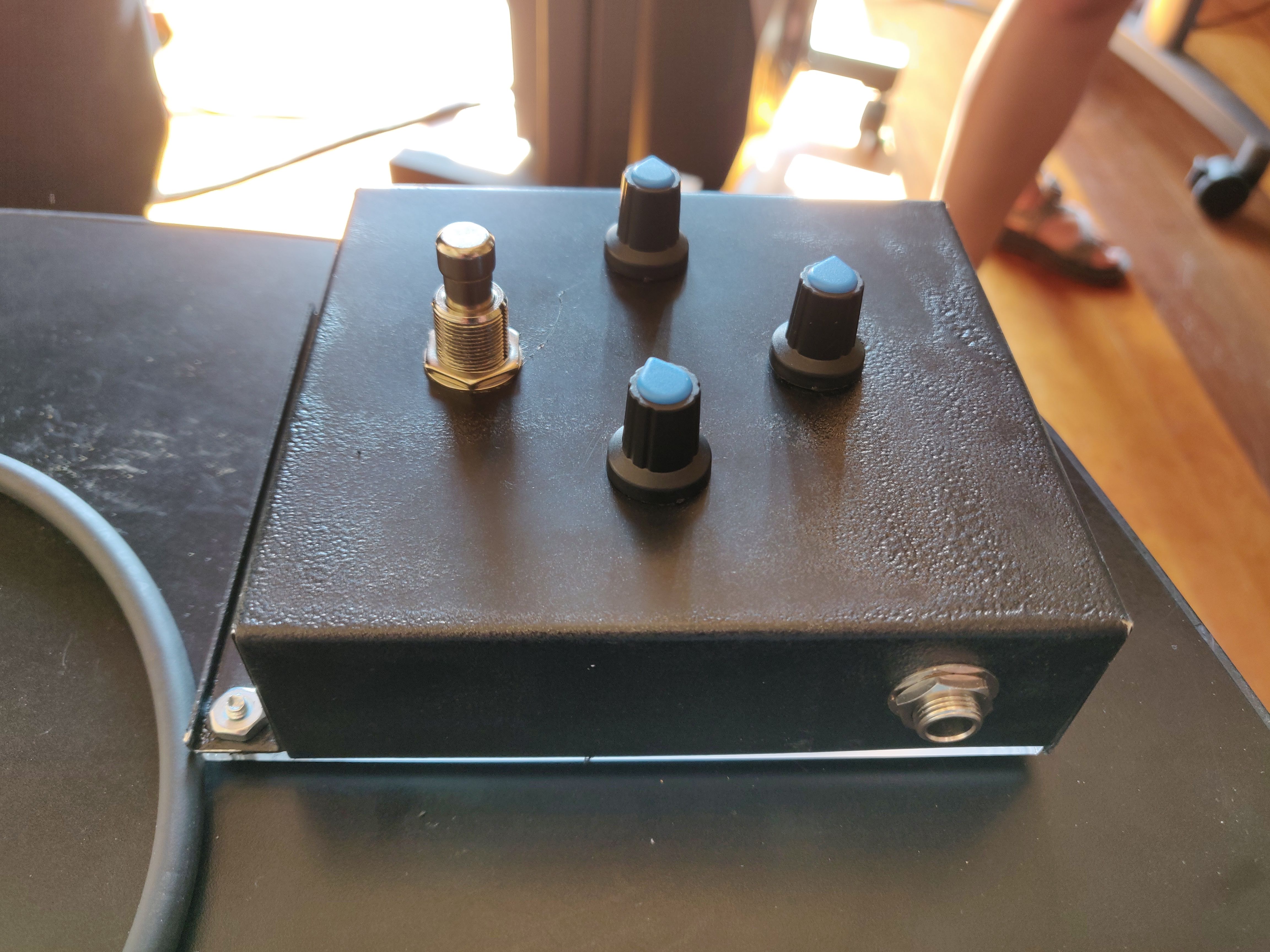
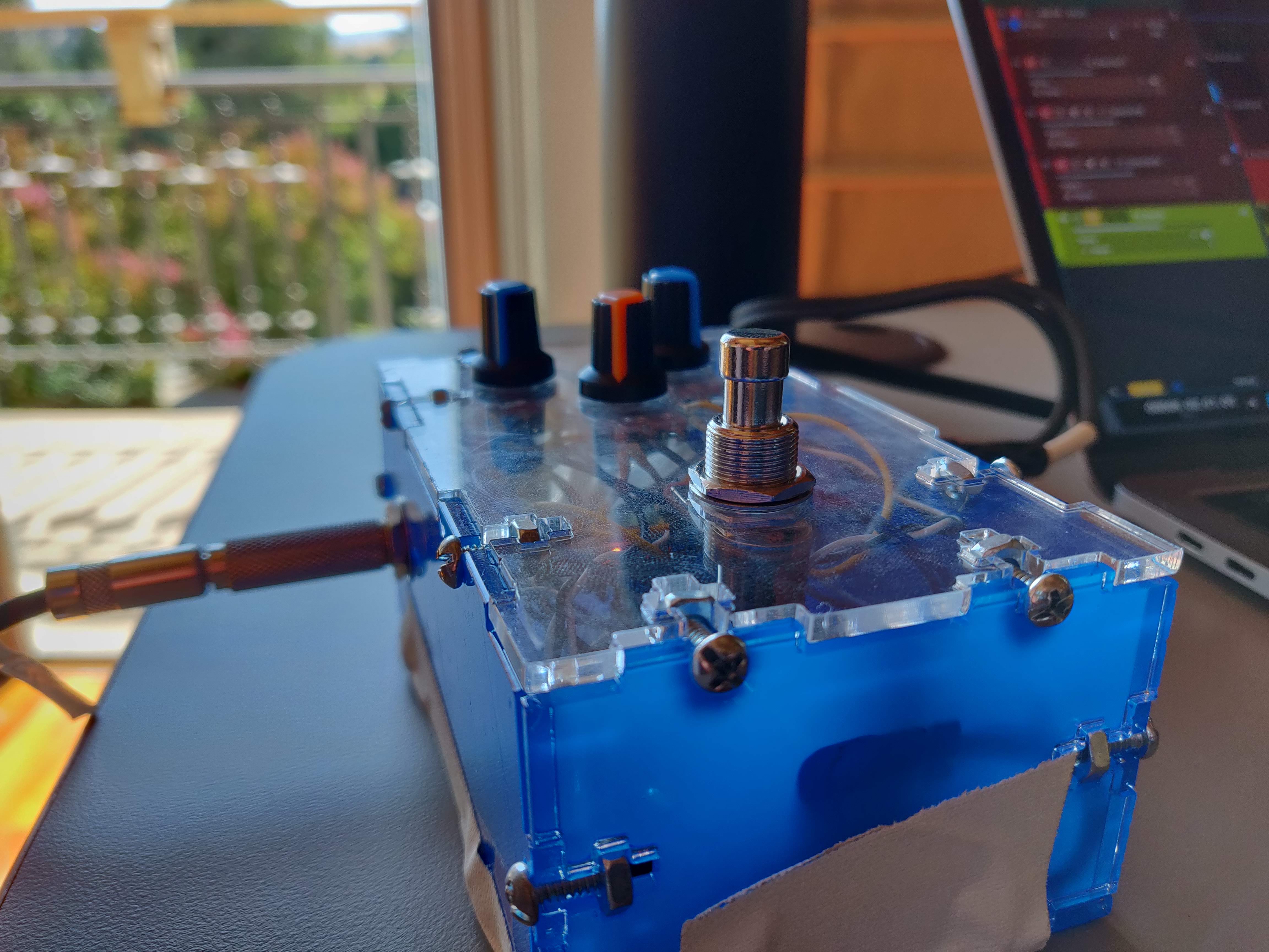
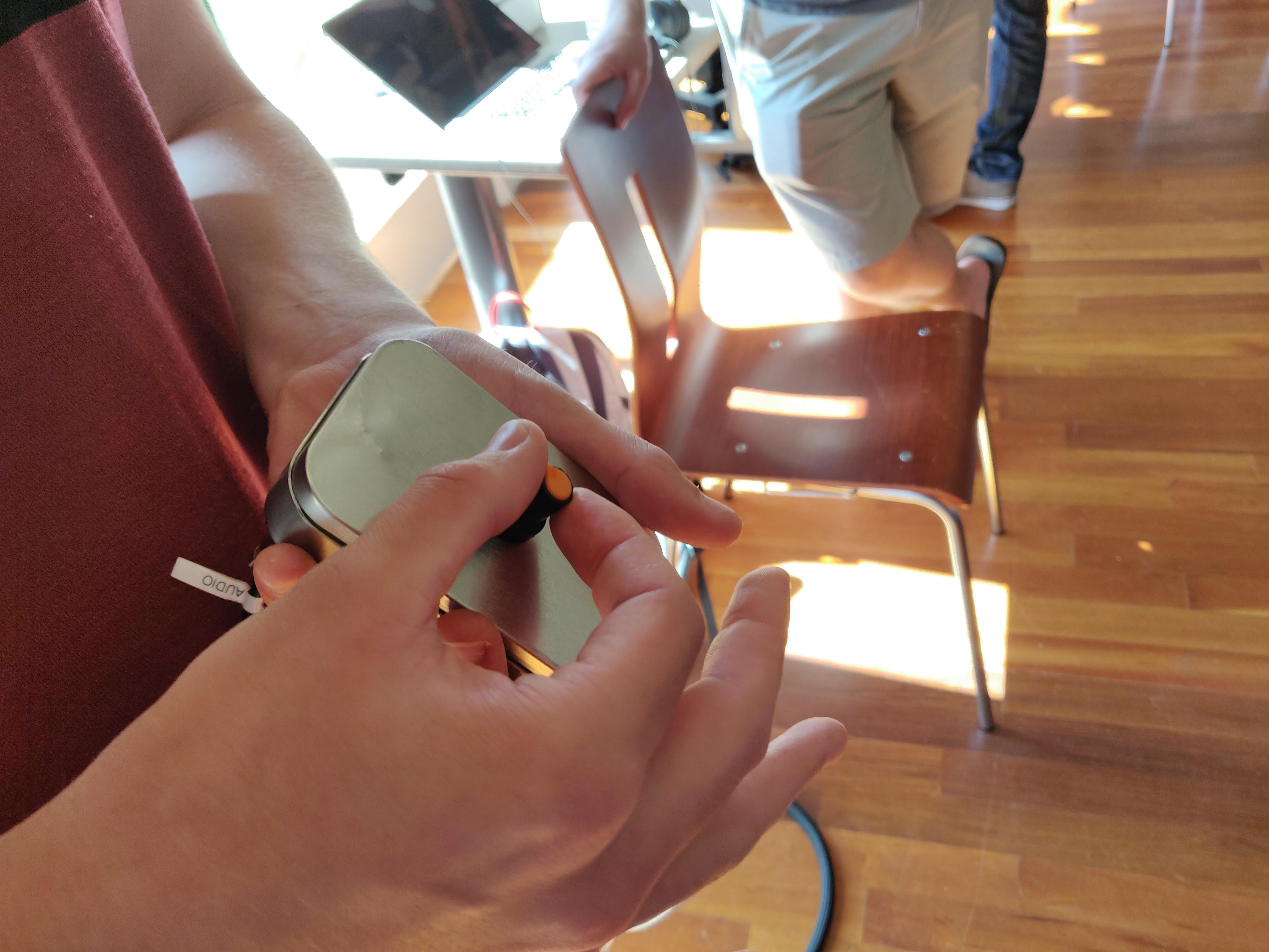
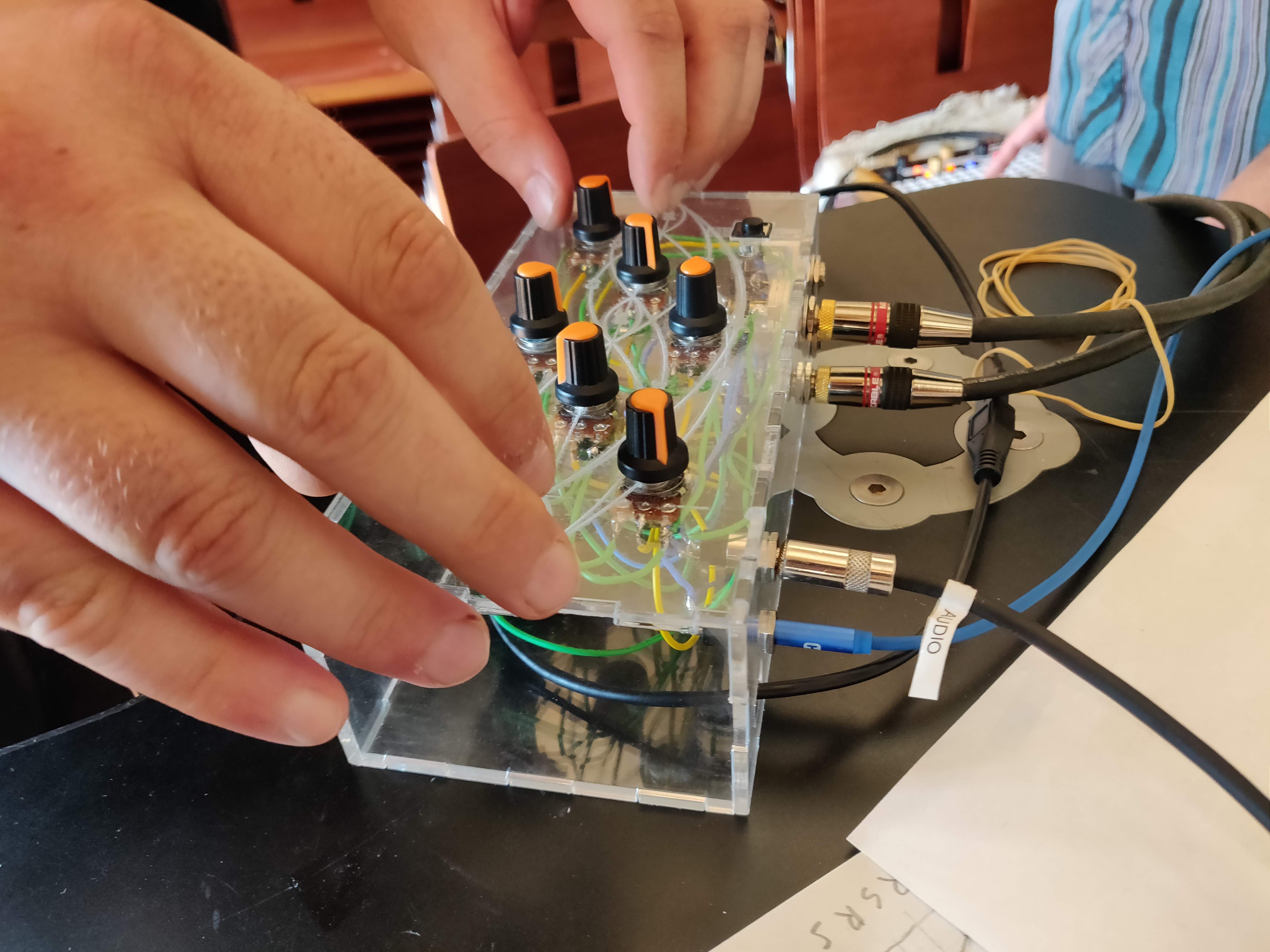
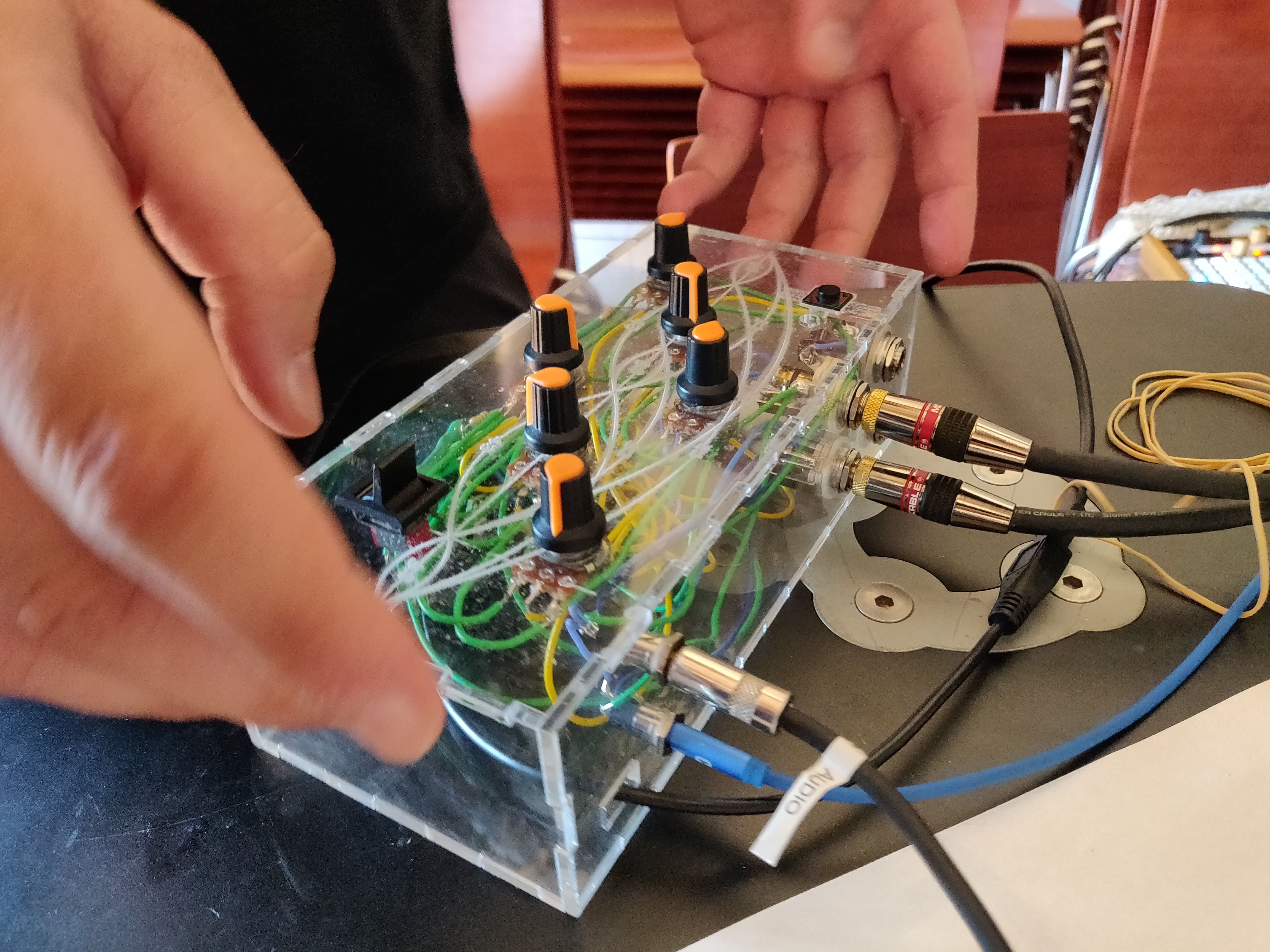
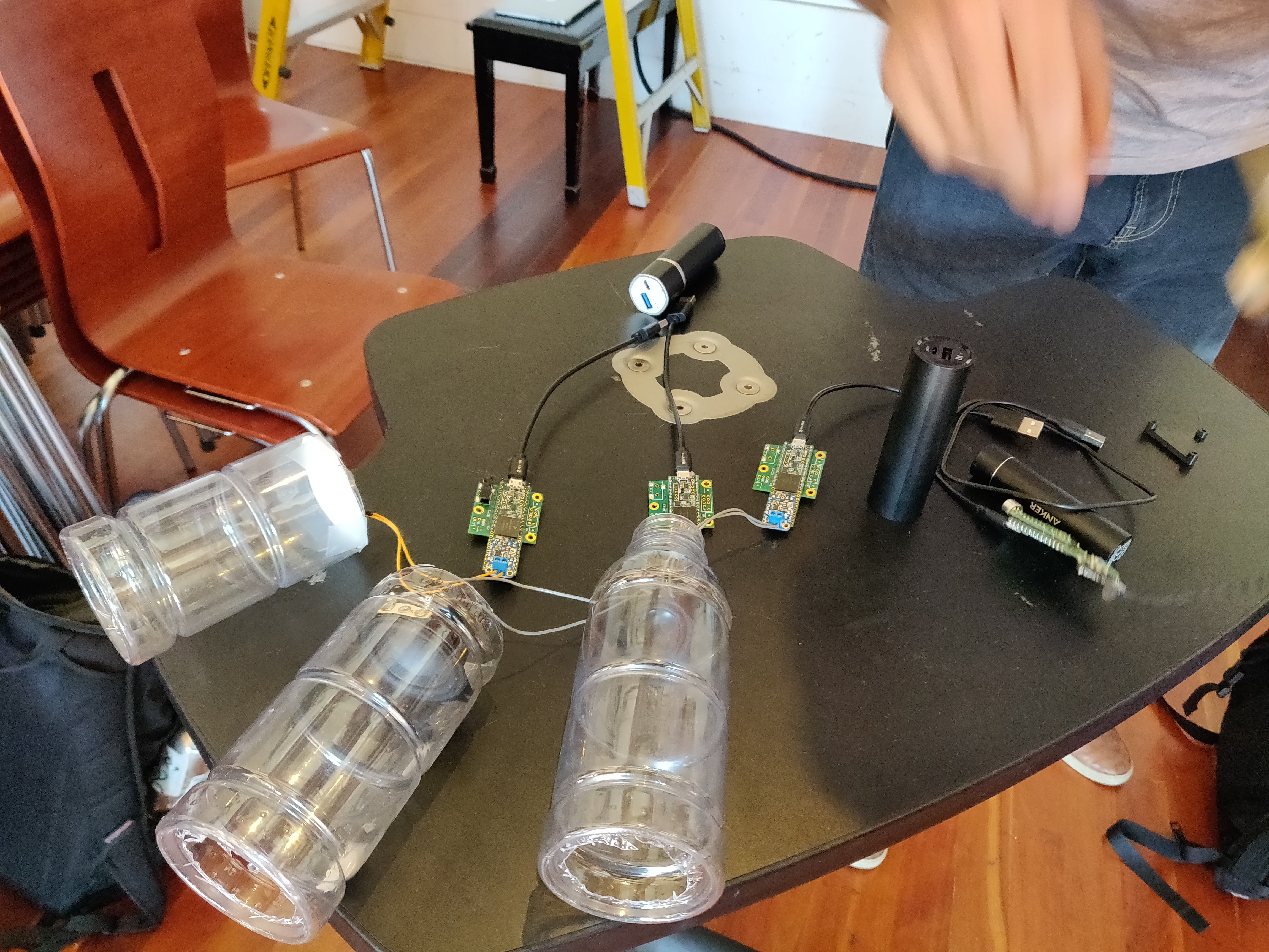
Final Projects
 |
 |
 |
 |
 |
 |
 |
 |
 |
 |
 |
 |
 |
 |
 |
 |
 |
 |
 |
 |
 |
 |
 |
 |
 |
 |
 |
 |
 |
 |
 |
 |
 |
 |
 |
 |
 |
 |
 |
Resources
Code from the Workshop
Faust Delay
import("stdfaust.lib");
delay(d) = de.delay(192000,d);
del = hslider("del(s)",1,0.001,1,0.001)*ma.SR : si.smoo;
gain = hslider("gain",1,0,1,0.01) : si.smoo;
process = delay(del)*gain;
Feed Forward Flanger & Tremolo
import("stdfaust.lib");
flanger(freq,wet,depth) = _ <: de.delay(256,d)*wet,_ :> /(2)
with{
    d = (os.osc(freq) + 1)*127*depth;
};
tremolo(freq,depth) = _*(1-(os.osc(freq)*0.5 + 0.5)*depth);
f = hslider("Frequency",10,0.1,100,0.01);
w = hslider("Wet",0.5,0,1,0.01);
d = hslider("Depth",0.5,0,1,0.01);
process = flanger(f,w,d) : tremolo(5,1) <: _,_;
Phasor
import("stdfaust.lib");
phasor(p) = _~(_+1)%p : _/p*2-1;
p = hslider("period",100,5,1000,0.01);
process = phasor(p);
Echo
import("stdfaust.lib");
echo(del,f) = +~de.delay(50000,d)*f
with{
    d = del*ma.SR;
};
process = echo(0.1,0.5);
Karplus-Strong
import("stdfaust.lib");
ks(freq,damping) = +~(de.fdelay4(1024,d)*damping : filter)
with{
    d = ma.SR/freq-1;
    filter = _ <: _',_ :> /(2);
};
excitation = button("gate") : ba.impulsify;
excitation2 = button("gate") : en.ar(0.001,0.001)*no.noise;
freq = hslider("freq",400,50,2000,0.01);
gain = hslider("gain",1,0,1,0.01);
process = excitation2*gain : ks(freq,0.99) <: _,_;
Switch From a Button on the Arduino
void setup() {
  Serial.begin(9600);
}

bool once = true;
bool change = true;

void loop() {
  int sensorValue = analogRead(A9);
  if(sensorValue > 50){
    if(once){
      if(change){
        Serial.println("on");
        change = false;
      }
      else{
        Serial.println("off");
        change = true;
      }
      once = false;
    }
  }
  else{
    once = true;
  }
  delay(10);
}
Pattern Matching/Iteration
import("stdfaust.lib");
synths(0) = os.osc(440);
synths(1) = os.sawtooth(440);
synths(2) = os.triangle(440);
/*
gains(0) = 0.5;
gains(1) = 0.67;
gains(2) = 0.76;
*/
gains(i) = ba.take(i+1,(0.5,0.67,0.76));
process = par(i,3,synths(i)*gains(i)) :> _;
Filter Bank
import("stdfaust.lib");
filterBank(N) = hgroup("FilterBank",seq(i,N,vgroup("band%i",fi.peak_eq(level(i),freq(i),300))))
with{
    level(j) = vslider("level%j",0,-90,12,0.01);
    freq(j) = vslider("freq%j[style:knob]",500*(j+1),50,5000,0.01);
};
process = filterBank(10);
Noise Gate
import("stdfaust.lib");
noiseGate(threshold,att) = _ <: _*(((abs(_) : si.smoo) < tLinear) : si.smooth(pole))
with{
    tLinear = threshold : ba.db2linear;
    pole = att : ba.tau2pole;
};
process = noiseGate(-30,0.001);
Sine Wave With Smaller Table Size
import("stdfaust.lib");
oscsin(freq) = rdtable(tablesize, os.sinwaveform(tablesize), int(os.phasor(tablesize,freq)))
with{
	tablesize = 1 << 10;
};
process = oscsin(440);
Low-Memory Footprint Zita
import("stdfaust.lib");

zita_rev_fdn(f1,f2,t60dc,t60m,fsmax) =
  ((si.bus(2*N) :> allpass_combs(N) : feedbackmatrix(N)) ~
   (delayfilters(N,freqs,durs) : fbdelaylines(N)))
with {
  N = 8;

  // Delay-line lengths in seconds:
  apdelays = (0.020346, 0.024421, 0.031604, 0.027333, 0.022904,
              0.029291, 0.013458, 0.019123); // feedforward delays in seconds
  tdelays = ( 0.153129, 0.210389, 0.127837, 0.256891, 0.174713,
              0.192303, 0.125000, 0.219991); // total delays in seconds
  tdelay(i) = floor(0.5 + ma.SR*ba.take(i+1,tdelays)); // samples
  apdelay(i) = floor(0.5 + ma.SR*ba.take(i+1,apdelays));
  fbdelay(i) = tdelay(i) - apdelay(i);
  // NOTE: Since SR is not bounded at compile time, we can't use it to
  // allocate delay lines; hence, the fsmax parameter:
  tdelaymaxfs(i) = floor(0.5 + fsmax*ba.take(i+1,tdelays));
  apdelaymaxfs(i) = floor(0.5 + fsmax*ba.take(i+1,apdelays));
  fbdelaymaxfs(i) = tdelaymaxfs(i) - apdelaymaxfs(i);
  nextpow2(x) = ceil(log(x)/log(2.0));
  maxapdelay(i) = int(2.0^max(1.0,nextpow2(apdelaymaxfs(i))));
  maxfbdelay(i) = int(2.0^max(1.0,nextpow2(fbdelaymaxfs(i))));

  apcoeff(i) = select2(i&1,0.6,-0.6);  // allpass comb-filter coefficient
  allpass_combs(N) =
    par(i,N,(fi.allpass_comb(maxapdelay(i),apdelay(i),apcoeff(i)))); // filters.lib
  fbdelaylines(N) = par(i,N,(de.delay(1024,(fbdelay(i)))));
  freqs = (f1,f2); durs = (t60dc,t60m);
  delayfilters(N,freqs,durs) = par(i,N,filter(i,freqs,durs));
  feedbackmatrix(N) = ro.hadamard(N);

  staynormal = 10.0^(-20); // let signals decay well below LSB, but not to zero

  special_lowpass(g,f) = si.smooth(p) with {
    // unity-dc-gain lowpass needs gain g at frequency f => quadratic formula:
    p = mbo2 - sqrt(max(0,mbo2*mbo2 - 1.0)); // other solution is unstable
    mbo2 = (1.0 - gs*c)/(1.0 - gs); // NOTE: must ensure |g|<1 (t60m finite)
    gs = g*g;
    c = cos(2.0*ma.PI*f/float(ma.SR));
  };

  filter(i,freqs,durs) = lowshelf_lowpass(i)/sqrt(float(N))+staynormal
  with {
    lowshelf_lowpass(i) = gM*low_shelf1_l(g0/gM,f(1)):special_lowpass(gM,f(2));
    low_shelf1_l(G0,fx,x) = x + (G0-1)*fi.lowpass(1,fx,x); // filters.lib
    g0 = g(0,i);
    gM = g(1,i);
    f(k) = ba.take(k,freqs);
    dur(j) = ba.take(j+1,durs);
    n60(j) = dur(j)*ma.SR; // decay time in samples
    g(j,i) = exp(-3.0*log(10.0)*tdelay(i)/n60(j));
  };
};

// Stereo input delay used by zita_rev1 in both stereo and ambisonics mode:
zita_in_delay(rdel) = zita_delay_mono(rdel), zita_delay_mono(rdel) with {
  zita_delay_mono(rdel) = de.delay(2700,ma.SR*rdel*0.001) * 0.3;
};

// Stereo input mapping used by zita_rev1 in both stereo and ambisonics mode:
zita_distrib2(N) = _,_ <: fanflip(N) with {
   fanflip(4) = _,_,*(-1),*(-1);
   fanflip(N) = fanflip(N/2),fanflip(N/2);
};

zita_rev1_stereo(rdel,f1,f2,t60dc,t60m,fsmax) =
   zita_in_delay(rdel)
 : zita_distrib2(N)
 : zita_rev_fdn(f1,f2,t60dc,t60m,fsmax)
 : output2(N)
with {
 N = 8;
 output2(N) = outmix(N) : *(t1),*(t1);
 t1 = 0.37; // zita-rev1 linearly ramps from 0 to t1 over one buffer
 outmix(4) = !,ro.butterfly(2),!; // probably the result of some experimenting!
 outmix(N) = outmix(N/2),par(i,N/2,!);
};

zita_light = hgroup("zita",(_,_ <: zita_rev1_stereo(rdel,f1,f2,t60dc,t60m,fsmax),_,_ :
	out_eq,_,_ : dry_wet : out_level))
with{
	fsmax = 48000.0;  // highest sampling rate that will be used
	rdel = 60;
	f1 = 200;
	t60dc = 3;
	t60m = 2;
	f2 = 6000;
	out_eq = pareq_stereo(eq1f,eq1l,eq1q) : pareq_stereo(eq2f,eq2l,eq2q);
	pareq_stereo(eqf,eql,Q) = fi.peak_eq_rm(eql,eqf,tpbt), fi.peak_eq_rm(eql,eqf,tpbt)
	with {
		tpbt = wcT/sqrt(max(0,g)); // tan(PI*B/SR), B bw in Hz (Q^2 ~ g/4)
		wcT = 2*ma.PI*eqf/ma.SR;  // peak frequency in rad/sample
		g = ba.db2linear(eql); // peak gain
	};
	eq1f = 315;
	eq1l = 0;
	eq1q = 3;
	eq2f = 1500;
	eq2l = 0;
	eq2q = 3;
	dry_wet(x,y) = *(wet) + dry*x, *(wet) + dry*y
	with {
		wet = 0.5*(drywet+1.0);
		dry = 1.0-wet;
	};
	drywet = vslider("dryWet",
		0,-1.0,1.0,0.01) : si.smoo;
	gain = vslider("level", -6, -70, 40, 0.1) : ba.db2linear : si.smoo;
	out_level = *(gain),*(gain);
};

process = zita_light;
Embedded Systems for Low-Latency Audio DSP
Synth Module Circuitry
The workshop lab kit contains the core elements to make a eurorack module. However, some circuitry needs to be added to the Teensy and its audio shield in order to implement voltage control (VC) or to interface (i.e., impedance matching, etc.) its audio inputs and outputs with other eurorack modules. This short section provides some schematics and useful information on how to do this.
NOTE: some of the figures presented in this section were freely inspired by resources available on the OWL project GitHub. Additional information might be found there as well.
M08X2
Eurorack modules are powered through a M08X2 port which can be found in their back. They carry 12v and 5v power as well as ground. It can be used as the power source for the various elements presented in the following sections as well as for the Teensy (+5V).
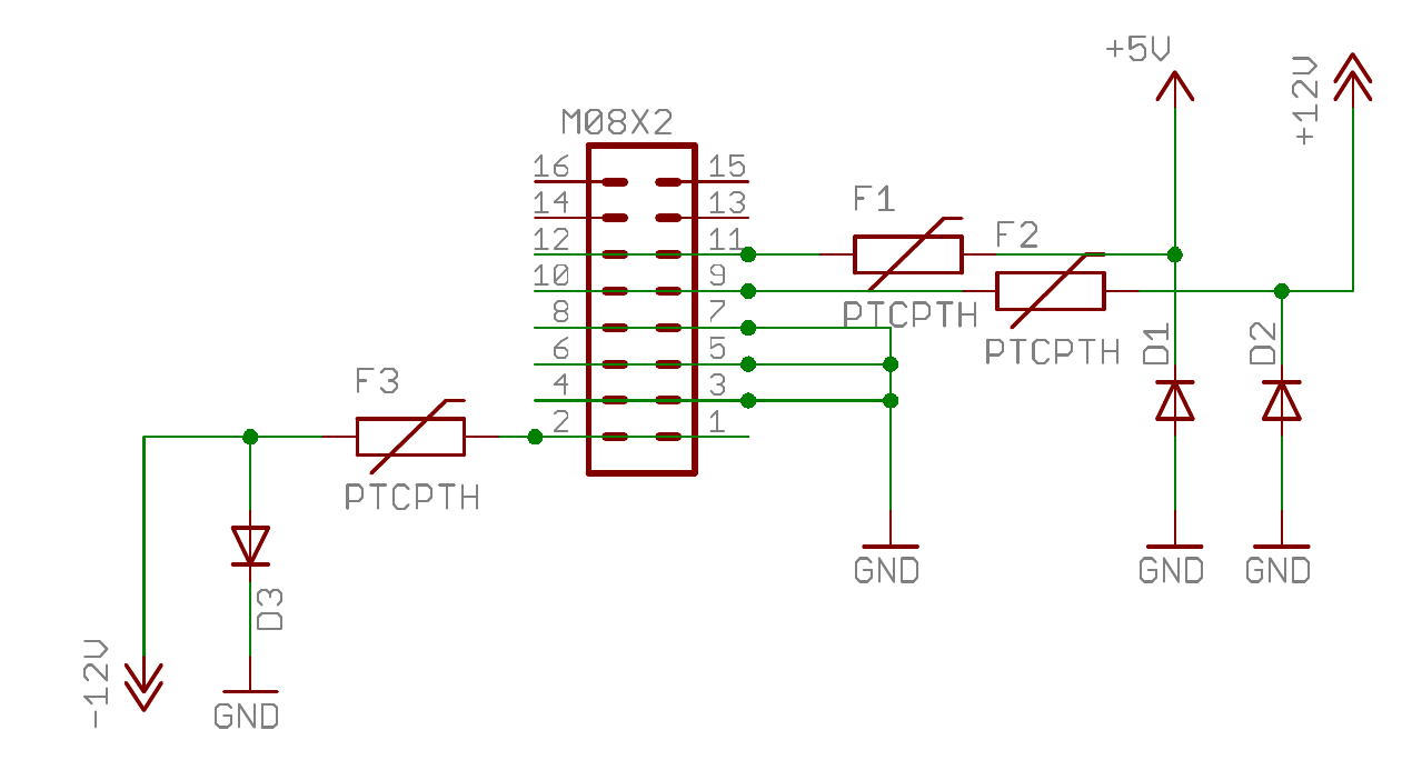
| Quantity | Part Type | Value | Part ID |
|---|---|---|---|
| 1 | M08X2 | M08X2 | M08X2 |
| 3 | Diode | 1N4001 | D1, D2, D3 |
| 3 | Fuse | PTCPTH | F1, F2, F3 |
Voltage Control (VC)
1/8" audio jack for voltage control can be connected to any of the analog input of the Teensy using the following circuit where ADC is the analog input on the Teensy and CV_D the audio jack. Power (i.e., -12V/+12V) and ground should be taken directly from the M08X2 port.

| Quantity | Part Type | Value | Part ID |
|---|---|---|---|
| 1 | 1/8" Jack Input | 1/8" Jack Input | CV_D |
| 2 | Potentiometer | Potentiometer | POT4, POT8 |
| 1 | Resistor | 100R | R805 |
| 1 | Resistor | 1k | R804 |
| 1 | Resistor | 68k | R803 |
| 1 | Resistor | 100k | R801 |
| 2 | Resistor | 240k | R800, R802 |
| 1 | Op-Amp | TL074 | IC2D |
| 1 | Diode | BAT54S | D800 |
Audio Input
Eurorack-compliant audio inputs can be implemented using the following circuit where Audio Jack should be the 1/8" audio jack input and Audio In one of the two audio line input on the Teensy Audio Shield. Power (i.e., -12V) and ground should be taken directly from the M08X2 port.
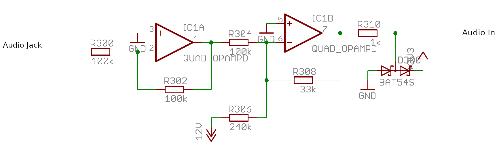
| Quantity | Part Type | Value | Part ID |
|---|---|---|---|
| 1 | 1/8" Jack Input | 1/8" Jack Input | CV_D |
| 1 | Resistor | 1k | R310 |
| 1 | Resistor | 33k | R308 |
| 3 | Resistor | 100k | R300, R302, R304 |
| 1 | Op-Amp | TL074 | IC2D |
| 1 | Diode | BAT54S | D300 |
Audio Output
Eurorack-compliant audio outputs can be implemented using the following circuit where Audio Jack should be the 1/8" audio jack output and Audio Out one of the two audio line output on the Teensy Audio Shield. Power (i.e., -12V) and ground should be taken directly from the M08X2 port.

| Quantity | Part Type | Value | Part ID |
|---|---|---|---|
| 1 | 1/8" Jack Input | 1/8" Jack Input | CV_D |
| 1 | Resistor | 100R | R406 |
| 1 | Resistor | 1k | R400 |
| 1 | Resistor | 3k3 | R404 |
| 1 | Resistor | 6k8 | R402 |
| 1 | Op-Amp | TL074 | IC2D |