Often the sound output of a physical model is associated with only a local
measurement made at a point on the simulated instrument. For example, in a
simplified sense, the output signal of an electric guitar is the velocity of a
small portion of the string directly above the pickup sensor. In our case, we choose to ``listen'' to the virtual
signal defined by the displacement of the string at the position ![]() meters
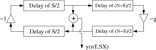
from the left end of the string. Due to (1), this
is the sum of the contents of the delay lines at the respective position. One
way to represent this is to split the delay lines and add a summing junction to
the block diagram as shown in Figure 6. Note that the
total delay around the loop of delay lines is still
meters
from the left end of the string. Due to (1), this
is the sum of the contents of the delay lines at the respective position. One
way to represent this is to split the delay lines and add a summing junction to
the block diagram as shown in Figure 6. Note that the
total delay around the loop of delay lines is still
![]() samples.
samples.