More Sensors
Contents
Piezo Pickups
Piezo elements are used like a contact microphone. The material (crystal) forces electrons to move when it is shocked or vibrates. We connect two leads to it, which then can be amplified and smoothed with filters, making it more usable.
Accelerometers
Quadrature Encoder
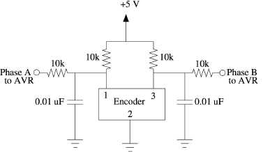
The above diagram demonstrates two signals in a quadrature relationship. The most common sensor we use that has this kind of signal is a rotary encoder or shaft encoder. Rotary encoders are normally optical (expensive) or mechanical (cheap). A mechanical encoder works simply by connecting the Phase A and Phase B pins (pins 1 and 3 in the diagram below) to a common pin (pin 2), according to a quadrature pattern. Wired up as in the diagram, pins 1 and 3 will go to ground when when connected to pin 2, and will be high when they are not. Mechanical contacts inside the encoder create the quadrature signals as above. An optical encoder may function similarly using LEDs and phototransistors as in the IR sensor above, with alternating dark/light patterns applied in quadrature.
Note that Phase A leads Phase B by 90 degrees when looking from left to right. Looking from right to left the opposite is true. We use quadrature encoders with the external interrupt on a microcontroller. By connecting the Phase A pin to an interrupt, we can generate an interrupt SIGNAL (function call) every time it transitions from low to high. In the interrupt, we can check the state of the Phase B pin. If B is low when A goes high, then we have moved to the right. If B is high when A goes high, then we know we have moved to the left. Shaft encoders are rated with a number of counts or ticks per complete rotation. Note that if we attach both Phase B and Phase A to external interrupts, we can double the resolution.
This filter circuit helps to stabilize the output of the shaft encoder and reduces noise by introducing pull-up resistors and low pass filters with cut-off frequency of ~ 1.6kHz on each of the two output pins.
Features
Features
Shaft encoders normally turn infinitely. If we know the number of counts, we can keep track of the absolute position of the shaft. By measuring the time between ticks (or between some number of ticks), we can calculate velocity. Also, using an IR reflective object sensor and some custom printed paper, for example, you can build your own quadrature encoder. There is NO A/D conversion involved in using a shaft encoder! Shaft encoders are commonly used in automation and robotics conjunction with motors to achieve accurate positioning. They are also ubiquitous on volume knobs in stereo equipment.
Motors/PWM
Motors can also be controlled my the AVR. There are some extra parts involved. Foremost of course is a DC motor. It also needs a motor controller, which supplies the needed voltage and current to the motor.
LED intensity, too!

