7745 Breadboarding lab
Breadboarding lab: Controlling an Physical Models using Breadboarded Sensors
Designed by Edgar Berdahl
For this lab you need your Satellite CCRMA kit, a laptop computer with Ethernet adaptor to program it, and some headphones with a mini 1/8" (2.54mm) stereo jack.
Note: In this lab, the images will show the Beagle Board xM instead of the Raspberry Pi, but actually all of the wiring is essentially the same.
Contents
Power Connections
- In order to run circuits on the breadboard, you need to get power to it. The Arduino gets 5V from the USB connection, so in this section you will make the 5V accessible to the breadboard.
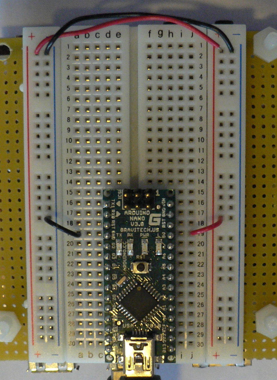
- Make sure that your Arduino is mounted at the very end of the breadboard with the higher-numbered rows, as shown in the following picture. In that case, the GND and 5V pins will end up in the 19th row. (Otherwise if your Arduino isn't mounted this way, you simply won't be able to rely on the row numbers, but you can still figure out how to wire things up!)
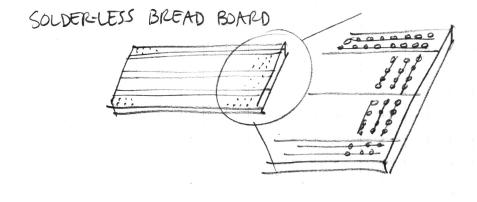
- Recall first that that holes in the solderless bread board are wired together as shown:
- Using short jumpers, connect the GND row to the blue "GND" bus on the breadboard, and connect the 5V row to the red "power" bus on the breadboard.
- Connect the "GND" and "power" busses from both sides of the breadboard together as shown.
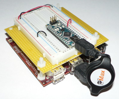
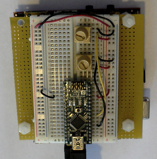
Viewed from further away, your breadboard should now look like the following:
First Circuit: Potentiometer
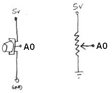
Now you will build the following voltage divider circuit, to connect one potentiometer to analog input A0.
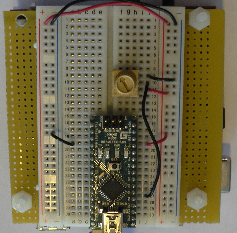
For some help on placing the wires, please see the following picture. In order to ensure the correct orientation, ensure that the text on the potentiometer is facing away from the Arduino (see also oblique picture in next section).
Add A Second Potentiometer
Now connect a second potentiometer to analog input A3 using the same voltage divider circuit.
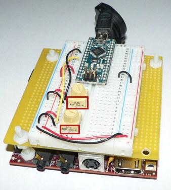
Again, ensure that the text on the potentiometer is facing *away* from the Arduino (see the red boxes in the following figure):
Optional: Build A New Effect
- Build a new effect whose parameters are adjustable by the potentiometers and button. We will ask for volunteers to demonstrate this the following morning in class. You can build on what you did in lab 1 if you like.
- Think about the result
- do the controls allow the entire space of parameters to be explored?
- is it easy to choose any desired set of parameters?
- does the effect sound good?
- does it have dynamics?
- would you want to use it live?
- If not, what is missing still?
Important Note
Some small amount of the text and images here was taken from prior laboratory exercises for the course Music 250A. We regret that we do not know who contributed these elements, but these people are likely to include Wendy Ju, Bill Verplank, Michael Gurevich, and possibly more.
