Difference between revisions of "250a Firmware Lab"
(→The ccrma@satellite setup) |
(→Powering Up For The First Time) |
||
| Line 21: | Line 21: | ||
== Powering Up For The First Time == | == Powering Up For The First Time == | ||
| − | '''When using your kit, always plug in the power to the USB hub before you plug in the power to the beagleboard.''' Otherwise, | + | '''When using your kit, always plug in the power to the USB hub before you plug in the power to the beagleboard.''' Otherwise, the Arduino Nano might fail to register its USB connection with the Beagleboard. So first power up the USB hub with the 5V adaptor with the smaller connector, and then power up the Beagleboard itself by the other 5V power adaptor into the Beagleboard. You will see some lights turn on, flickering every now and then. This means that ccrma@satellite is booting up. |
== Connect To ccrma@satellite == | == Connect To ccrma@satellite == | ||
Revision as of 10:30, 6 October 2010
Lab 3: Beagleboard and Firmware Programming
Due on Wednesday, October 13th at 5PM
For this lab you need your MaxKit, and Pd on a computer. During this lab, you will assemble your ccrma@satellite kit and start to use it.
Contents
- 1 The ccrma@satellite setup
- 2 Powering Up For The First Time
- 3 Connect To ccrma@satellite
- 4 Never Power Down the Board Without Halting it First!
- 5 Getting Comfortable With ccrma@satellite
- 6 Optional: Programming Linux
- 7 Custom Communication
- 8 Low-latency sensing
- 9 Autonomous ccrma@satellite
- 10 Halt Your Board Properly When Finished!
The ccrma@satellite setup
First, you'll need to set up your beagleboard, USB hub, and breadboard on a foamcore base. Included in your kit, you should have:
- White USB hub with RJ45 Ethernet jack
- Beagleboard
- A 4GB SD card to plug into the beagleboard
- Two 5V power adaptors (one for the Beagleboard and one for the USB hub)
- One Ethernet cable
- Arduino Nano (from your old kit)
- A GT Max adjustable-length USB cable to connect the Arduino to the hub
If you are missing something, please go get it before assembling your kit.
[insert photo of the CCRMA Satellite set up here]
Powering Up For The First Time
When using your kit, always plug in the power to the USB hub before you plug in the power to the beagleboard. Otherwise, the Arduino Nano might fail to register its USB connection with the Beagleboard. So first power up the USB hub with the 5V adaptor with the smaller connector, and then power up the Beagleboard itself by the other 5V power adaptor into the Beagleboard. You will see some lights turn on, flickering every now and then. This means that ccrma@satellite is booting up.
Connect To ccrma@satellite
In order to see what your ccrma@satellite kit is doing, you need to log in to it. To do so, connect the USB hub to your laptop using the Ethernet cable and remotely open an SSH window on ccrma@satellite.
Never Power Down the Board Without Halting it First!
Would you take the battery out of your laptop and unplug its power adaptor without shutting down? I don't think so! The same goes for ccrma@satellite because it is a small computer running linux. If you power if off without shutting down, then you can corrupt the files on the SD card, which in the worst case could cause it to stop booting up anymore, and we would have to burn you a new SD card! So just remember this: HALT ccrma@satellite BEFORE DISCONNECTING IT FROM ITS POWER!
Now we will test the halt procedure. Run the halt command as superuser by typing sudo halt at the ccrma@satellite prompt. Then you will again have to type in the password temppwd in order to have the privilege to run this command. The SSH connection will be closed, but it will still be 20 seconds or so before ccrma@satellite has completely shut down. (Note: The command sudo reboot would instead have caused ccrma@satellite to reboot itself.)
Wait an extra entire minute to ensure that ccrma@satellite is shut down. However, it will not power itself off. To do this, you need to disconnect the two 5V power adaptors.
Getting Comfortable With ccrma@satellite
Power up ccrma@satellite again using the same procedure as before, where you plug in the power to the USB hub first, and then following that you plug the power into the beagleboard itself. After about 30 seconds, the board should be booted up again, so you can log in again by running the command
ssh -X ccrma@192.168.1.105
If you list the device directory, you can see which devices are attached to linux. Type
ls /dev
to get an idea. Wow, there are so many! To list the devices with serial interfaces type
ls /dev/tty*
Once of these devices should be /dev/ttyUSB0 for the Arduino Nano. If you do not see this one, then try rebooting using sudo reboot to see if that fixes this problem. (If you reboot, this will take about 45 seconds, and you will have to login again using ssh. If that doesn't work, come talk to us. To try to debug the problem yourself, type dmesg and look at the result.)
Optional: Programming Linux
Since ccrma@satellite runs ubuntu linux on an OMAP chip, many standard software packages have been compiled for it. This is why we were easily able to install software such as Jack, Audacity, ChucK, Faust, Jacktrip, and the Arduino software.
If you are lucky, you can install your favorite software using the apt-get utility. To get a list of packages available on the OMAP's ARM architecture, type
sudo apt-cache pkgnames
You will notice that this list is way too long to look at. You can pipe it to the text file using the command
sudo apt-cache pkgnames > packages.txt
and then look at it using emacs packages.txt, or you search for a particular package, such as
sudo apt-cache pkgnames | grep emacs.
Or, you can compile linux software yourself on the Beagleboard. The gcc, g++ tools etc. are already installed.
Type the df command. You can see that there is not a whole lot more than 1GB available on the SD card, so you should only install software if you decide that you need it.
Get Arduino up and running on the Beagleboard
At the command prompt, type Arduino.
Compiling and uploading firmware code in the Arduino Program
For this class, we assume that you will be adapting existing working code for your own applications. While this is certainly easier than writing firmware from scratch, it does require understanding how existing code functions.
Please upload the following firmware programs from your Arduino program's Sketchbook->Examples folders to your Arduino controller and see how they function. Do attach LEDs, buttons, as is appropriate:
* Digital->Blink
* Digital->BlinkWithoutDelay
* Digital->Button (Even though it works, there is a bug in this file. Can you find it?)
Custom Communication
Another reason that you might want to program the Arduino microcontroller even if you are connected to a laptop or desktop computer is to enable greater control over the communications from the Arduino. In this segment of the laboratory, we learn a wider variety of ways to send data from the Arduino hardware to the computer than we have previously used.
Serial communication with the Arduino software
You might have noticed in the previous lab segment that it can be very hard to know what is going wrong when the Arduino hardware is in autonomous mode. Here, we send serial communications between the Arduino hardware and the Arduino software.
- Sketchbook->Examples->Analog->Smoothing: Use the Serial Monitor (icon on the far left on the Arduino software toolbar) to get data back from the Arduino.
- Sketchbook->Examples->Communication->SerialCallandResponse.
Serial communication with PD
Now let's try using serial to communicate with PD.
First let's try outputting information to the Arduino hardware:
- Load Examples->Communication->PhysicalPixel
- The PD patch for communicating with this firmware is linked here; use "Save Link As" to save it to your lab3 directory. PhysicalPixel.pd
Next let's try getting information from the Arduino hardware:
- Load Examples->Communication->Graph
- The PD patch for communicating with this firmware is linked here; use "Save Link As" to save it to your lab3 directory. Graph.pd
Low-latency sensing
Encoder input
One final reason that you would want direct control over the Arduino firmware is that you might have very low-latency sensing needs. As an example of this, we show you here how to use encoder input with the Arduino.
Now you will learn how to use a rotary encoder. Quit Pd or Max/MSP. Then download encoder.zip and use the Arduino software to download the encoder.pde firmware file to your Arduino board.
Build this schematic: http://cm-wiki.stanford.edu/mediawiki/images/c/c1/Encoder_filter.png.
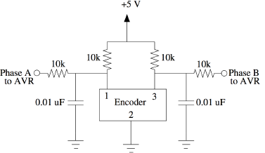
Connect pin 2 of the Arduino to Phase A. Connect pin 3 of the Arduino to Phase B, and you're ready to send out the position of the encoder over the serial bus.
You can read the values coming in from the encoder with the patches included in the ZIP file.
The values should start near zero and increase or decrease, depending on which direction you turn the encoder. How are negative numbers represented? Why does the encoder always start near 0 when the program on the Arduino is restarted?
Autonomous ccrma@satellite
We will now show you how to make your kit autonomous in the sense that it can operate all by itself, free from any external laptop computer. In this example, the Arduino runs the standard firmata firmware. In order to re-install this firmware, first load the Arduino software. Then load the StandardFirmata sketch by choosing File|Examples|Firmata|StandardFirmata. Make sure that you have the correct Serial Port and Board selected. Then upload StandardFirmata to your Arduino Nano by clicking on the Upload button. Check that there were no errors with uploading StandardFirmata before you quit the Arduino software.
To Enable A Default Patch On Boot
In the terminal, change to the on-startup directory by typing
cd ~/on-startup
and type ls -la to see what files are in there. You can see that the link (aka alias) default_patch.pd points to windy-day.pd. If you would like to look at the contents of this patch, you can start up Jack using qjackctl & and then load the patch in pd.
In order to enable the default patch to load on boot, rename the file load_default_patch_disabled to load_default_patch using the command
mv load_default_patch_disabled load_default patch
The cat command can be used to display the contents of any ASCII file. To look at the contents of load_default_patch, type cat load_default_patch. As you can see, it starts up Jack using the text-based jackd instead of qjackctl, and then it loads default_patch.pd in pd with the graphical user interface (GUI) disabled.
Now your kit should be ready for autonomous ccrma@satellite. To test it, just reboot the kit by typing sudo reboot and entering the password temppwd. As it is rebooting, plug a pair of ear buds, headphones, or loudspeakers into the 1/8" (2.54mm) jack labeled AUDIO OUT on the beagleboard. Within about a minute, your kit should be fully rebooted. To check this, you can try logging in with SSH. Either way, it should start running windy_day.pd upon startup.
Once your kit is fully rebooted, if you touch the anaog input pins on the Arduino A0-A7, it should start making some sound. However, unless you connect up a sensor circuit to some of the analog inputs, the exact behavior may be complicated. In particular, it will depend on the electrical properties of your body (how much sweat is on your fingers, whether you are touching a grounded device such as a laptop with any part of your body. Ask for help if you cannot get any sound.
Finally, log back into ccrma@satellite using the same command as always ssh -X ccrma@192.168.1.105. Type ps -A at the prompt to get a list of the currently running processes. jackd is the Jack audio sound server, and pdextended is the pd process. To stop the default patch from running, type ./stop_default. To see how stop_default works, type cat stop_default. (The ./ was necessary in order to run the script stop_default because the current user directory ~ is not in the user path, so linux needs the ./ to indicate to look for stop_default in the current directory.)
Now start up Jack by typing qjackctl & and clicking the Start button. Change to the on-startup directory by typing cd ~/on-startup, and load windy-day.pd in pd using the command pd windy-day.pd &. Edit it so that it does something very different. You are making your own, completely autonomous new music controller! Instead of submitting your actual pd patch (because this is a little bit involved), it is okay to simply include some text in your email to Ed and Wendy describing what your patch did. Also please write a few sentences about what part of the lab was the most difficult, and please document any bugs that you find so that we can fix them!
Thanks so much! We are looking forward to seeing demos of your new music controllers at the beginning of the next lab session!
Halt Your Board Properly When Finished!
Remember to shut down your board when you are done before powering it off! As described above, you can do this by executing the command sudo halt and then waiting 30 seconds before disconnecting the power cables.