Difference between revisions of "250a Firmware Lab"
m (→The Autonomous Arduino) |
|||
| (186 intermediate revisions by 4 users not shown) | |||
| Line 1: | Line 1: | ||
| − | + | <font size=5>Lab 3: Firmware Programming</font><br> | |
| − | <font size=5>Lab 3: Firmware Programming/font><br> | + | See [https://ccrma.stanford.edu/courses/250a/schedule.html this quarter's schedule] for due dates. |
| − | + | ||
| − | For this lab you need your [[MaxKit]], | + | For this lab you need your [[MaxKit]], with your Satellite CCRMA . |
| − | |||
| − | |||
| − | |||
| − | |||
| − | |||
| + | == Firmware Programming On Arduino == | ||
=== Compiling and uploading firmware code in the Arduino Program === | === Compiling and uploading firmware code in the Arduino Program === | ||
| − | For this class, we assume that you will be adapting existing working code for your own applications. While this is certainly easier than writing firmware from scratch, it does require understanding how existing code functions. | + | For this class, we assume that you will be adapting existing working code for your own applications. While this is certainly easier than writing firmware from scratch, it does require understanding how existing code functions. |
| − | + | ||
| − | + | ||
| − | + | ||
| − | + | ||
| − | + | ||
| − | + | ||
| − | + | ||
| − | + | ||
| − | + | ||
| − | + | ||
| − | + | ||
| − | + | ||
| − | + | ||
| − | + | ||
| − | + | ||
| − | + | ||
| − | + | ||
| − | + | ||
| − | + | ||
| − | + | ||
| − | + | ||
| − | + | ||
| − | + | ||
| − | + | ||
| − | + | ||
| − | + | ||
| − | + | ||
| − | + | ||
| − | + | ||
| − | + | ||
| − | + | ||
| − | + | ||
| − | + | * Use the usual procedure (see [https://ccrma.stanford.edu/wiki/Software_Lab_250 described before]) to power up Satellite CCRMA and login as the user ''ccrma'' with the password ''temppwd''. | |
| − | * | + | * Make an empty directory for lab3 using |
| − | + | ''mkdir ~/lab3'' | |
| − | * | + | * Enter the lab3 directory by typing |
| − | + | ''cd ~/lab3'' | |
| − | + | * Download the first files for the lab using | |
| − | + | ''wget https://ccrma.stanford.edu/courses/250a/labs/lab3.zip | |
| + | * Unzip lab3 three with | ||
| − | + | ''unzip lab3.zip'' | |
| − | + | ||
| − | |||
| − | |||
| − | |||
| − | |||
| − | |||
| − | |||
| − | + | * Start the Arduino software by typing the command ''arduino &'' in the XTerminal to your Satellite. Please upload the following firmware programs from your Arduino program's Examples folders to your Arduino controller and see how they function. Do attach LEDs, buttons, as is appropriate: | |
| − | + | * Examples->Digital->Blink | |
| + | * Examples->Digital->BlinkWithoutDelay | ||
| + | * Examples->Digital->Button | ||
| − | + | == Custom Communication == | |
| + | One reason that you might want to program the Arduino microcontroller is to enable greater control over the communications from the Arduino. In this segment of the laboratory, we learn a wider variety of ways to send data from the Arduino hardware to the computer than we have previously used. | ||
| − | === | + | === Serial communication with the Arduino Serial Monitor === |
| + | You might have noticed in the previous lab segment that it can be very hard to know what is going wrong when the Arduino hardware is in autonomous mode. Here, we send serial communications between the Arduino hardware and the Arduino IDE. | ||
| − | + | * Examples->Analog->Smoothing: Use the Serial Monitor (icon on the far left on the Arduino IDE toolbar) to get data back from the Arduino. When you do this, you'll notice the TX light on the Arduino lights up and stays lit. | |
| − | + | The high datarate on the Serial monitor can make the Xwindow for the program freeze. If the Arduino IDE crashes, go to the main terminal and type 'fg' to bring the arduino to the foreground, and then type 'cntl-x, cntl-c' to kill the program. Now add a delay to the loop function to prevent the freeze. <span style="color:green;">What size delay makes for speedy updates but doesn't cause freezing?</span> | |
| − | + | * Examples->Communication->SerialCallandResponseASCII. This will show you how to do two-way communication with the Serial Monitor. | |
| − | === | + | === Serial communication with PD === |
| + | Now let's try using serial to communicate with PD. | ||
| − | + | First let's try outputting information to the Arduino hardware: | |
| + | * In Arduino, load Examples->Communication->PhysicalPixel | ||
| + | ** The PD patch for communicating with this firmware is lab3/physicalpixel.pd. | ||
| + | ** You may need to hunt for the right serial port to make this work. Serial port 4 worked for us... | ||
| − | |||
| − | * In | + | Next let's try getting information from the Arduino hardware: |
| + | * In Arduino, load Examples->Communication->Graph | ||
| + | ** The PD patch for communicating with this firmware is lab3/Graph.pd | ||
| + | ** Again, you need to set the right serial port, ascii/binary, and graph on/off settings. | ||
| + | == Low-latency sensing == | ||
| + | === Encoder input === | ||
| − | + | * Download example firmware for interfacing with a rotary encoder using the command | |
| − | + | ''wget ccrma.stanford.edu/courses/250a/labs/files/encoder2011.zip'' | |
| − | + | (Or use scp, Fetch, or your favorite secure FTP program to get encoder2011.zip onto your kit.) | |
| − | + | * Extract the ZIP file by typing | |
| − | + | ||
| − | + | ||
| − | + | ''unzip encoder2011.zip'' | |
| − | + | * Enter the encoder2011 subdirectory by executing | |
| − | + | ''cd encoder2011'' | |
| − | |||
| − | |||
| − | + | One final reason that you would want direct control over the Arduino firmware is that you might have very low-latency sensing needs. As an example of this, we show you here how to use encoder input with the Arduino. | |
| − | + | * Quit Pd to ensure that Pd isn't using the USB/serial connection to the Arduino. | |
| − | + | * Start up the Arduino software using the command ''arduino &'' and upload the sketch ''~/lab3/encoder2011/encoder/encoder.pde'' to the Arduino. Then quit the Arduino IDE and start up Pd by typing ''pd encoder.pd'' | |
| − | + | * Now you need to build this schematic to interface the encoder: http://cm-wiki.stanford.edu/mediawiki/images/c/c1/Encoder_filter.png. | |
| + | Pin two is the middle pin on the rotary encoder, and pins 1 and 3 are the other directly adjacent pins. It can be a bit difficult to plug the encoder into the solderless protoboard, but you can do it if you straighten out the pins first. | ||
| − | In | + | Note: In the schematic, ''AVR Phase A'' is digital pin 2 or the Arduino, and ''AVR Phase B'' is digital pin 3. |
| − | + | Now you're ready to send out the position of the encoder over the serial bus. The values should start near zero and increase or decrease, depending on which direction you turn the encoder. <span style="color:green;">How are negative numbers represented? Why does the encoder always start near 0 when the program on the Arduino is restarted?</span> | |
| − | + | ||
| − | + | ||
| + | == Make A Musical Interaction == | ||
| + | As the final main deliverable of the lab, you should cause your Satellite CCRMA kit make some sound that depends on how you manipulate the sensors. For example, you could make a musical instrument, a music controller, a mock-up sound art installation, or some other sonic interaction. Now that you have had some experience synthesizing sound, your sound synthesis patch should involve more than just a few ''osc~''s. Think about what you want to design before you get started. | ||
| + | For your musical interaction, you can write your own firmware, or you can use Firmata. If you choose to use Firmata, then you need to re-flash Firmata to the Arduino. (See [https://ccrma.stanford.edu/wiki/Talk:250a_Microcontroller_%26_Sensors_Lab_Pd#Prepare_Arduino instructions from Lab 2].) | ||
| + | Start up the Jack audio server by executing the command ''qjackctl &'' at the terminal and clicking on the ''Start'' button. In order to be able to hear audio, you will need to plug a pair of ear buds, headphones, or loudspeakers into the 1/8" (2.54mm) jack labeled AUDIO OUT on the beagleboard. | ||
| + | It is probably easiest to make your patch by modifying ''~/on-startup/windy-day.pd'', which Edgar demonstrated in class. To start it up, first change to the directory ''~/on-startup'' by typing ''cd ~/on-startup'' in the terminal. Then type ''pd windy-day.pd &'' to startup ''pd''. | ||
| − | + | <span style="color:green;">Don't forget to make a video of your musical interaction!</span> | |
| − | + | <!-- == Optional: Autonomous Satellite CCRMA == | |
| + | By this point you should be done with your musical interaction. If you would like to go the extra mile, we will now show you how to make your musical interaction autonomous in the sense that it can operate all by itself, free from any external laptop computer. We will show you how to do this using the example ''windy-day.pd''. | ||
| − | === | + | === To Enable A Default Patch On Boot === |
| − | + | * First put StandardFirmata back on the Arduino as described in lab 2. | |
| − | + | * In the terminal, change to the ''on-startup'' directory by typing | |
| + | ''cd ~/on-startup'' | ||
| − | + | * The files need to be updated. You can do this by running the command | |
| − | + | ''wget ccrma.stanford.edu/courses/250a/labs/files/newonstartupfiles.zip'' | |
| − | + | and then | |
| − | + | ''unzip newonstartupfiles.zip'' | |
| − | + | ||
| − | + | ||
| − | + | and agree to replace the files in question. | |
| − | + | ||
| − | |||
| − | + | * Now, type ''ls -la'' to see what files are in there. You can see that the link (aka alias) ''default_patch.pd'' points to ''windy-day.pd''. In order to enable the default patch to load on boot, rename the file ''load_default_patch_disabled'' to ''load_default_patch'' using the command | |
| − | + | ''mv load_default_patch_disabled load_default patch'' | |
| − | + | * The ''cat'' command can be used to display the contents of any ASCII file. To look at the contents of ''load_default_patch'', type ''cat load_default_patch''. As you can see, it starts up Jack using the text-based ''jackd'' instead of ''qjackctl'', and then it loads ''default_patch.pd'' in pd with the graphical user interface (GUI) disabled. | |
| − | Now | + | * Now your kit should be ready for autonomous Satellite CCRMA. To test it, just reboot the kit by typing ''sudo reboot'' and entering the password ''temppwd''. As it is rebooting, plug a pair of ear buds, headphones, or loudspeakers into the 1/8" (2.54mm) jack labeled AUDIO OUT on the beagleboard. Within about a minute, your kit should be fully rebooted. To check this, you can try logging in with SSH. Either way, it should start running ''windy_day.pd'' upon startup. |
| − | + | * Once your kit is fully rebooted, if you touch the anaog input pins on the Arduino A0-A7, it should start making some sound. However, unless you connect up a sensor circuit to some of the analog inputs, the exact behavior may be complicated. In particular, it will depend on the electrical properties of your body (how much sweat is on your fingers, whether you are touching a grounded device such as a laptop with any part of your body. Ask for help if you cannot get any sound. | |
| − | + | * Finally, log back into your Satellite. Type ''ps -A'' at the prompt to get a list of the currently running processes. ''jackd'' is the Jack audio sound server, and ''pdextended'' is the pd process. To stop the default patch from running, type ''stop_default''. To see how ''stop_default'' works, type ''cat ~/on-startup/stop_default''. | |
| + | --> | ||
| + | == Optional: Programming Linux == | ||
| + | '''We don't actually expect you to do anything here, we are just providing some more information that is maybe helpful for you linux gurus.''' Since Satellite CCRMA runs Ubuntu linux on an OMAP chip, many standard software packages have been compiled for it. This is why we were easily able to install software such as Jack, [http://audacity.sourceforge.net/ Audacity], [http://chuck.cs.princeton.edu/ ChucK], [http://faust.grame.fr/ Faust], [https://ccrma.stanford.edu/groups/soundwire/software/jacktrip/ Jacktrip], and the Arduino software. | ||
| − | + | If you are lucky, you can install your favorite software using the ''apt-get'' utility. To get a list of packages available on the OMAP's ARM architecture, type | |
| − | + | ''sudo apt-cache pkgnames'' | |
| − | + | You will notice that this list is way too long to look at. You can pipe it to the text file using the command | |
| − | + | ''sudo apt-cache pkgnames > packages.txt'' | |
| − | + | and then look at it using ''emacs packages.txt'', or you search for a particular package, such as | |
| − | + | ''sudo apt-cache pkgnames | grep emacs''. | |
| − | + | Or, you can compile linux software yourself on the Satellite. The gcc, g++ tools etc. are already installed. | |
| − | + | Type the ''df'' command. You can see that there is not a whole lot more than 1GB available on the SD card, so you should only install software if you decide that you need it. | |
| − | + | ||
| − | |||
| − | |||
| − | |||
| − | |||
| − | |||
| − | |||
| − | |||
[[Category:250a]][[Category:PID]] | [[Category:250a]][[Category:PID]] | ||
Latest revision as of 10:35, 26 September 2012
Lab 3: Firmware Programming
See this quarter's schedule for due dates.
For this lab you need your MaxKit, with your Satellite CCRMA .
Contents
Firmware Programming On Arduino
Compiling and uploading firmware code in the Arduino Program
For this class, we assume that you will be adapting existing working code for your own applications. While this is certainly easier than writing firmware from scratch, it does require understanding how existing code functions.
- Use the usual procedure (see described before) to power up Satellite CCRMA and login as the user ccrma with the password temppwd.
- Make an empty directory for lab3 using
mkdir ~/lab3
- Enter the lab3 directory by typing
cd ~/lab3
- Download the first files for the lab using
wget https://ccrma.stanford.edu/courses/250a/labs/lab3.zip
- Unzip lab3 three with
unzip lab3.zip
- Start the Arduino software by typing the command arduino & in the XTerminal to your Satellite. Please upload the following firmware programs from your Arduino program's Examples folders to your Arduino controller and see how they function. Do attach LEDs, buttons, as is appropriate:
* Examples->Digital->Blink
* Examples->Digital->BlinkWithoutDelay
* Examples->Digital->Button
Custom Communication
One reason that you might want to program the Arduino microcontroller is to enable greater control over the communications from the Arduino. In this segment of the laboratory, we learn a wider variety of ways to send data from the Arduino hardware to the computer than we have previously used.
Serial communication with the Arduino Serial Monitor
You might have noticed in the previous lab segment that it can be very hard to know what is going wrong when the Arduino hardware is in autonomous mode. Here, we send serial communications between the Arduino hardware and the Arduino IDE.
- Examples->Analog->Smoothing: Use the Serial Monitor (icon on the far left on the Arduino IDE toolbar) to get data back from the Arduino. When you do this, you'll notice the TX light on the Arduino lights up and stays lit.
The high datarate on the Serial monitor can make the Xwindow for the program freeze. If the Arduino IDE crashes, go to the main terminal and type 'fg' to bring the arduino to the foreground, and then type 'cntl-x, cntl-c' to kill the program. Now add a delay to the loop function to prevent the freeze. What size delay makes for speedy updates but doesn't cause freezing?
- Examples->Communication->SerialCallandResponseASCII. This will show you how to do two-way communication with the Serial Monitor.
Serial communication with PD
Now let's try using serial to communicate with PD.
First let's try outputting information to the Arduino hardware:
- In Arduino, load Examples->Communication->PhysicalPixel
- The PD patch for communicating with this firmware is lab3/physicalpixel.pd.
- You may need to hunt for the right serial port to make this work. Serial port 4 worked for us...
Next let's try getting information from the Arduino hardware:
- In Arduino, load Examples->Communication->Graph
- The PD patch for communicating with this firmware is lab3/Graph.pd
- Again, you need to set the right serial port, ascii/binary, and graph on/off settings.
Low-latency sensing
Encoder input
- Download example firmware for interfacing with a rotary encoder using the command
wget ccrma.stanford.edu/courses/250a/labs/files/encoder2011.zip
(Or use scp, Fetch, or your favorite secure FTP program to get encoder2011.zip onto your kit.)
- Extract the ZIP file by typing
unzip encoder2011.zip
- Enter the encoder2011 subdirectory by executing
cd encoder2011
One final reason that you would want direct control over the Arduino firmware is that you might have very low-latency sensing needs. As an example of this, we show you here how to use encoder input with the Arduino.
- Quit Pd to ensure that Pd isn't using the USB/serial connection to the Arduino.
- Start up the Arduino software using the command arduino & and upload the sketch ~/lab3/encoder2011/encoder/encoder.pde to the Arduino. Then quit the Arduino IDE and start up Pd by typing pd encoder.pd
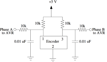
- Now you need to build this schematic to interface the encoder: http://cm-wiki.stanford.edu/mediawiki/images/c/c1/Encoder_filter.png.
Pin two is the middle pin on the rotary encoder, and pins 1 and 3 are the other directly adjacent pins. It can be a bit difficult to plug the encoder into the solderless protoboard, but you can do it if you straighten out the pins first.
Note: In the schematic, AVR Phase A is digital pin 2 or the Arduino, and AVR Phase B is digital pin 3.
Now you're ready to send out the position of the encoder over the serial bus. The values should start near zero and increase or decrease, depending on which direction you turn the encoder. How are negative numbers represented? Why does the encoder always start near 0 when the program on the Arduino is restarted?
Make A Musical Interaction
As the final main deliverable of the lab, you should cause your Satellite CCRMA kit make some sound that depends on how you manipulate the sensors. For example, you could make a musical instrument, a music controller, a mock-up sound art installation, or some other sonic interaction. Now that you have had some experience synthesizing sound, your sound synthesis patch should involve more than just a few osc~s. Think about what you want to design before you get started.
For your musical interaction, you can write your own firmware, or you can use Firmata. If you choose to use Firmata, then you need to re-flash Firmata to the Arduino. (See instructions from Lab 2.)
Start up the Jack audio server by executing the command qjackctl & at the terminal and clicking on the Start button. In order to be able to hear audio, you will need to plug a pair of ear buds, headphones, or loudspeakers into the 1/8" (2.54mm) jack labeled AUDIO OUT on the beagleboard.
It is probably easiest to make your patch by modifying ~/on-startup/windy-day.pd, which Edgar demonstrated in class. To start it up, first change to the directory ~/on-startup by typing cd ~/on-startup in the terminal. Then type pd windy-day.pd & to startup pd.
Don't forget to make a video of your musical interaction!
Optional: Programming Linux
We don't actually expect you to do anything here, we are just providing some more information that is maybe helpful for you linux gurus. Since Satellite CCRMA runs Ubuntu linux on an OMAP chip, many standard software packages have been compiled for it. This is why we were easily able to install software such as Jack, Audacity, ChucK, Faust, Jacktrip, and the Arduino software.
If you are lucky, you can install your favorite software using the apt-get utility. To get a list of packages available on the OMAP's ARM architecture, type
sudo apt-cache pkgnames
You will notice that this list is way too long to look at. You can pipe it to the text file using the command
sudo apt-cache pkgnames > packages.txt
and then look at it using emacs packages.txt, or you search for a particular package, such as
sudo apt-cache pkgnames | grep emacs.
Or, you can compile linux software yourself on the Satellite. The gcc, g++ tools etc. are already installed.
Type the df command. You can see that there is not a whole lot more than 1GB available on the SD card, so you should only install software if you decide that you need it.