Difference between revisions of "250a Firmware Lab"
(→The ccrma@satellite setup) |
(→The ccrma@satellite setup) |
||
| Line 20: | Line 20: | ||
[insert photo of the CCRMA Satellite set up here] | [insert photo of the CCRMA Satellite set up here] | ||
| − | When using your kit, always plug in the power to the USB hub before you plug in the power to the beagleboard. | + | == Powering Up For The First Time == |
| + | '''When using your kit, always plug in the power to the USB hub before you plug in the power to the beagleboard.''' Otherwise, it can happen that the Arduino Nano is not initialized properly. So first power up the USB hub with the 5V adaptor with the smaller connector, and then power up the beagleboard itself by the other 5V power adaptor into the beagleboard. You will see some lights turn on, flickering every now and then. This means that ccrma@satellite is booting up. | ||
| + | |||
| + | == Connect To ccrma@satellite == | ||
| + | In order to see what your ccrma@satellite kit is doing, you need to log in to it. To do so, connect the USB hub to your laptop using the Ethernet cable and [https://ccrma.stanford.edu/wiki/CCRMA_Satellite_How_To_Connect remotely open an SSH window on ccrma@satellite]. | ||
| + | |||
| + | == Never Power Off The Board Without Halting It First == | ||
| + | Would you take the battery out of your laptop and unplug its power adaptor without shutting down? ''I don't think so!'' The same goes for ccrma@satellite because it is a small computer running linux. If you power if off without shutting down, then you can corrupt the files on the SD card, which in the worst case could cause it to stop booting up anymore, and we would have to burn you a new SD card! So just remember this: '''Halt ccrma@satellite before disconnecting it from its power!''' | ||
| + | |||
| + | |||
Now connect your computer so that you can talk to ccrma@satellite. | Now connect your computer so that you can talk to ccrma@satellite. | ||
Revision as of 19:23, 4 October 2010
Lab 3: Beagleboard and Firmware Programming
Due on Wednesday, October 13th at 5PM
For this lab you need your MaxKit, and Pd on a computer. During this lab, you will assemble your ccrma@satellite kit and start to use it.
Contents
The ccrma@satellite setup
First, you'll need to set up your beagleboard, USB hub, and breadboard on a foamcore base. Included in your kit, you should have:
- White USB hub with RJ45 Ethernet jack
- Beagleboard
- A 4GB SD card to plug into the beagleboard
- Two 5V power adaptors (one for the Beagleboard and one for the USB hub)
- One Ethernet cable
- Arduino Nano (from your old kit)
- A GT Max adjustable-length USB cable to connect the Arduino to the hub
If you are missing something, please go get it before assembling you kit.
[insert photo of the CCRMA Satellite set up here]
Powering Up For The First Time
When using your kit, always plug in the power to the USB hub before you plug in the power to the beagleboard. Otherwise, it can happen that the Arduino Nano is not initialized properly. So first power up the USB hub with the 5V adaptor with the smaller connector, and then power up the beagleboard itself by the other 5V power adaptor into the beagleboard. You will see some lights turn on, flickering every now and then. This means that ccrma@satellite is booting up.
Connect To ccrma@satellite
In order to see what your ccrma@satellite kit is doing, you need to log in to it. To do so, connect the USB hub to your laptop using the Ethernet cable and remotely open an SSH window on ccrma@satellite.
Never Power Off The Board Without Halting It First
Would you take the battery out of your laptop and unplug its power adaptor without shutting down? I don't think so! The same goes for ccrma@satellite because it is a small computer running linux. If you power if off without shutting down, then you can corrupt the files on the SD card, which in the worst case could cause it to stop booting up anymore, and we would have to burn you a new SD card! So just remember this: Halt ccrma@satellite before disconnecting it from its power!
Now connect your computer so that you can talk to ccrma@satellite.
[more detailed information on setting up Xterm connection]
[try running some normal Unix programs so that you feel like this is in fact Unix]
Get Arduino up and running on the Beagleboard
At the command prompt, type Arduino.
Compiling and uploading firmware code in the Arduino Program
For this class, we assume that you will be adapting existing working code for your own applications. While this is certainly easier than writing firmware from scratch, it does require understanding how existing code functions.
Please upload the following firmware programs from your Arduino program's Sketchbook->Examples folders to your Arduino controller and see how they function. Do attach LEDs, buttons, as is appropriate:
* Digital->Blink
* Digital->BlinkWithoutDelay
* Analog->Fading
* Digital->Button (Even though it works, there is a bug in this file. Can you find it?)
Modify the following programs:
- Digital->Melody: Use the piezo speakers supplied with the lab for this one (there are some already wired in a drawer marked "speakers" in the lab). Change the song. Incorporate some user interaction so that the song does not loop endlessly.
- Analog->AnalogInput: Change the code so that you create a digital metronome whose speed can be controlled by a continuous sensor.
Custom Communication
Another reason that you might want to program the Arduino microcontroller even if you are connected to a laptop or desktop computer is to enable greater control over the communications from the Arduino. In this segment of the laboratory, we learn a wider variety of ways to send data from the Arduino hardware to the computer than we have previously used.
Serial communication with the Arduino software
You might have noticed in the previous lab segment that it can be very hard to know what is going wrong when the Arduino hardware is in autonomous mode. Here, we send serial communications between the Arduino hardware and the Arduino software.
- Sketchbook->Examples->Analog->Smoothing: Use the Serial Monitor (icon on the far left on the Arduino software toolbar) to get data back from the Arduino.
- Sketchbook->Examples->Communication->SerialCallandResponse.
Serial communication with PD
Now let's try using serial to communicate with PD.
First let's try outputting information to the Arduino hardware:
- Load Examples->Communication->PhysicalPixel
- The PD patch for communicating with this firmware is linked here; use "Save Link As" to save it to your lab3 directory. PhysicalPixel.pd
Next let's try getting information from the Arduino hardware:
- Load Examples->Communication->Graph
- The PD patch for communicating with this firmware is linked here; use "Save Link As" to save it to your lab3 directory. Graph.pd
Low-latency sensing
Encoder input
One final reason that you would want direct control over the Arduino firmware is that you might have very low-latency sensing needs. As an example of this, we show you here how to use encoder input with the Arduino.
Now you will learn how to use a rotary encoder. Quit Pd or Max/MSP. Then download encoder.zip and use the Arduino software to download the encoder.pde firmware file to your Arduino board.
Build this schematic: http://cm-wiki.stanford.edu/mediawiki/images/c/c1/Encoder_filter.png.
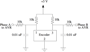
Connect pin 2 of the Arduino to Phase A. Connect pin 3 of the Arduino to Phase B, and you're ready to send out the position of the encoder over the serial bus.
You can read the values coming in from the encoder with the patches included in the ZIP file.
The values should start near zero and increase or decrease, depending on which direction you turn the encoder. How are negative numbers represented? Why does the encoder always start near 0 when the program on the Arduino is restarted?
Sensor instrument, optimized (optional)
Now, try reimplementing your instrument from the end of Lab 2 in firmware! Program the Arduino firmware so that it only detects inputs and performs outputs to the pins you use, and modify your Lab 2 patch to work with it.
Your code on the Arduino should be running your program a lot faster than Firmata. Does your instrument work any better?
Reaction time sensing (optional)
For the very ambitious: Write a program that tests how fast people can respond to light vs. sound trigger! Please include your code in your lab write-up.
Restore Firmata?
If, after all of this, you just long for the halcyon days where you just had to program in Max or PD, you are welcome to reflash your Arduino hardware with the Firmata software.
In your lab write-up, please say something about whether you preferred using Firmata (like in Lab 2) or writing your own firmware (like in this lab). Our feelings will not be hurt! We just want to know how you feel...